6 Martin
®
MAC One User Manual Rev. B
Connecting to data
Warning! Before installing the MAC One, read the latest version of the fixture’s Safety and Installation
Manual that is attached to the User Manual, paying particular attention to the ‘Safety Precautions’ section.
Besides important safety information, the Safety and Installation Manual contains instructions for
connecting to AC mains power.
If independent control of a fixture is required, it must have its own DMX channels. Fixtures that are
required to behave identically can share the same DMX address and channels.
The number of fixtures that you can connect to DMX data in a daisy chain is limited by the number of DMX
channels required by the fixtures. A maximum of 512 channels is available in one DMX universe. To add
more fixtures or groups of fixtures when you no longer have enough DMX channels, add a DMX universe
and another daisy-chained link.
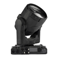
The MAC One has two pairs of connectors for control data In/Out:
• one pair of locking 5-pin XLR sockets, and
• one pair of etherCON sockets.
Data via DMX cable
The MAC One has 5-pin locking XLR sockets for DMX and RDM input and output via DMX cable. The pin-
out on both sockets is:
• Pin 1 to shield
• Pin 2 to data 1 cold (-)
• Pin 3 to data 1 hot (+).
Pins 4 and 5 are not used by the fixture but are bridged between input and output sockets. These pins can
therefore be used as a pass-through connection for an additional data signal if required.
Tips for reliable data transmission via DMX cable
• Use shielded twisted-pair high-quality DMX cable.
• 24 AWG cable is suitable for runs up to 300 meters (1000 ft). Heavier gauge cable and/or an amplifier
is recommended for longer runs.
• Do not use microphone cable, as standard microphone cable does not have the correct impedance and
cannot transmit control data reliably over long runs.
• To split the data link into branches, use an optically isolated splitter-amplifier. Use an RDM-compatible
splitter-amplifier if using RDM.
• Do not overload the DMX data link. You can connect up to a maximum of 32 devices on a serial DMX
link.
• Install a DMX termination plug at the end of the DMX link.
Connecting to data via DMX cable
To connect the fixture to DMX and/or RDM data carried over DMX cable:
1. Connect the DMX data output from the controller to the fixture’s data input (male XLR) socket using
good-quality DMX cable.
2. Run DMX cable from the fixture’s data output (female XLR) socket to the data input of the next fixture
and continue until the link is complete.
3. Terminate the data link by connecting a 120 Ohm, 0.25 Watt resistor between the data 1 hot (+) and
cold (-) conductors at the end of the link. If the link is divided into branches using a DMX splitter,
terminate each branch of the link.