8 P3-100 user manual
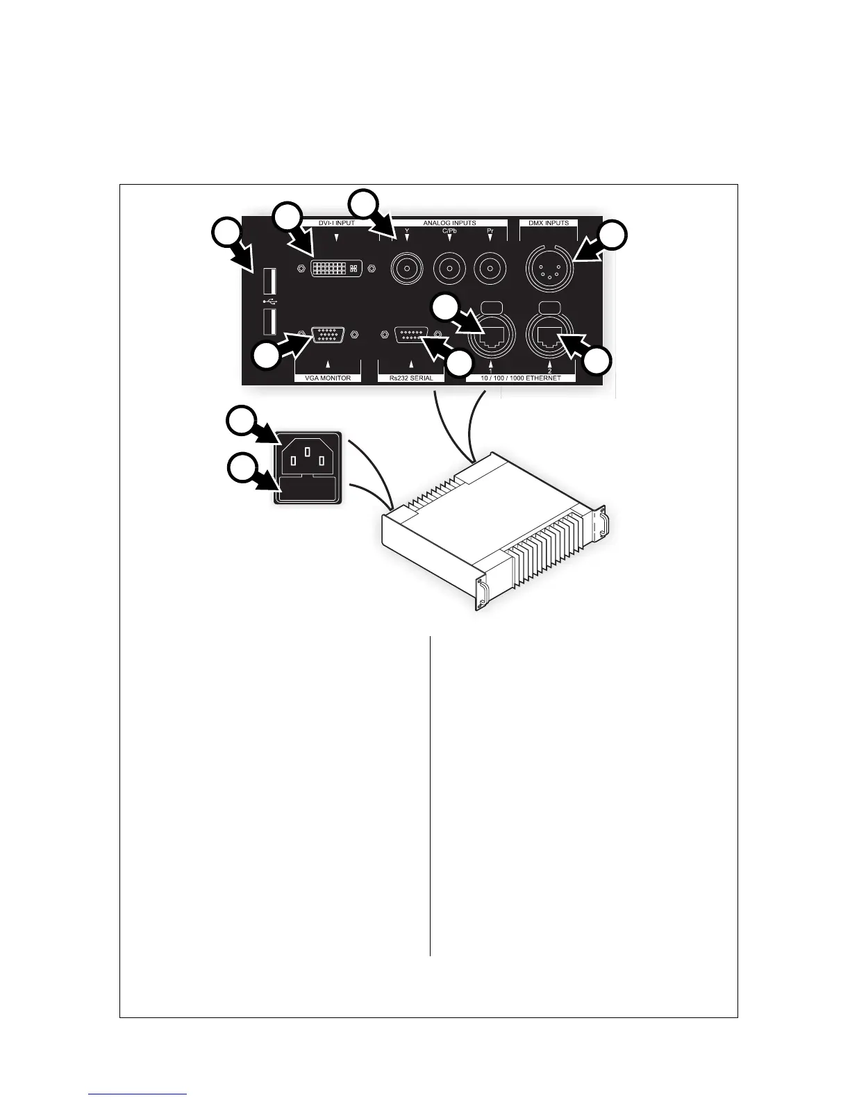
Connections panel
A - Power input (male IEC socket)
Accepts AC mains power at 115 - 250 V,
47 - 63 Hz.
B - Fuseholder
Install a 1 A, T (time delay) fuse only.
C - USB ports
For mouse, keyboard, USB memory device, etc.
D - DVI-I input
For digital video input only (DVI-D).
E - Analog video inputs (BNC connectors)
RCA-to-BNC or S-video-to-RCA adapters will be
required if your analog video cable does not have
BNC connectors.
• Use the Y connector for composite video.
• Use the Y and C/Pb connectors for S-Video.
•Use the Y, C/Pb and Pr connectors for
component video. Typical connector color
coding is Green to Y, Blue to Pb and Red to
Pr.
F - DMX input (5-pin locking XLR)
For connection from a DMX controller.
G - Ethernet port 2 – P3 output (RJ-45)
P3 signal output. Connect to the video panel
installation via an Ethernet cable.
H - Ethernet port 1 (RJ-45)
Communication with P3-100’s internal webserver
for retrieval of status information.
I - Serial data port (RS-232)
Available for future data connection options.
J - VGA monitor out (DE15)
For connection to an analog monitor (XGA
1024x768 or better).
Figure 2: Connections panel overview
A
B
C
D
E
F
G
I
J
H