Martindale ET4000 / ET4500 Measurements
32
5.3 Resistance of earth connection and equipotential
bonding
The resistance measurement is performed to ensure the protective measures against
electric shock through earth connections and bonding are effective. The following
continuity sub-functions are available:
r1
rN
r2
R1+R2
R2
R1+RN
R LOW
Continuity.
It is important to select the appropriate sub-function in order to correctly classify the
measurement when entering it into the required verification documents (Electrical
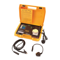
Installation Certificate, Periodic Inspection Report etc.). The r1, rN, r2, R1+R2 and R2
continuity tests are carried out between the L and PE terminals in the same way
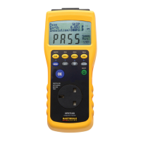
regardless of which sub-function is selected. The R1+RN, R LOW and Continuity tests
are carried out between the L and N terminals.
These measurements must only be performed on de-energized circuits and
equipment!
See chapter 4.3 Function selection for instructions
on key functionality.
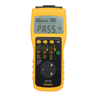
Figure 5.8: R2 continuity
Figure 5.9: 200 mA RLOW Ω
Test parameters for resistance measurement
Test
Resistance measurement sub-function [r1, rN, r2, R1+R2, R2, R1+RN,
R LOW, CONTINUITY]
Limit
Setting range [OFF, 0.1 Ω - 20.0 Ω]
Additional test parameter for Continuity sub-function
Buzzer On (sounds if resistance is lower than the set limit value)