Martindale ET4000 / ET4500 Measurements
50
U
n
Input voltage range (L-N or L1-L2)
110 V
(93 V U
L-N
134 V)
230 V
(185 V U
L-N
266 V)
400 V
(321 V U
L-L
485 V)
Testing considerations
Large fluctuations of mains voltage can influence the measurement results (the
noise sign is displayed in the message field). In this case it is recommended
that the measurements are repeated a few times to check if the readings are
stable.
When measuring Z
Line-Line
with the instrument test leads PE and N connected
together the instrument will display a warning of a dangerous PE voltage. The
measurement will be performed anyway.
The specified accuracy of the tested parameters is valid only if the mains voltage
is stable during the measurement.
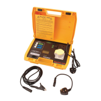
5.6.2 Voltage drop
The voltage drop is calculated and is based on the difference between the line
impedance at the connection point (sockets) and the line impedance at the reference
point (usually at the switchboard).
Circuits for measurement of voltage drop
Figure 5.32: Phase-neutral or phase-phase voltage drop measurement
Voltage drop measurement procedure
Step 1: Measuring the impedance Zref at the origin
Select the Z LINE function using the function selector switch.
Set sub-function to ΔU using UP / DOWN keys.
Select test parameters (optional).
Connect the test leads to the instrument.
Connect the test leads to the origin of the electrical installation (see Step 1 of
Figure 5.33).
Press the NULL key to perform the measurement.