Martindale ET4000 / ET4500 Measurements
49
5.6.1 Line impedance and prospective short circuit current
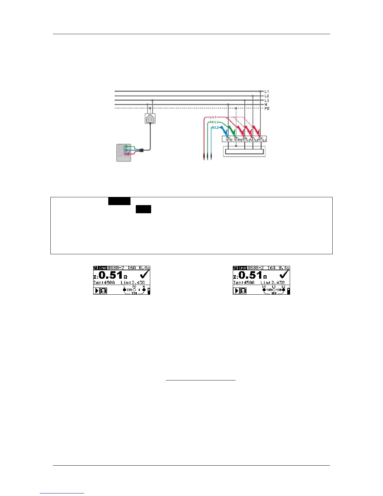
Circuits for measurement of line impedance
Figure 5.30: Phase-neutral or phase-phase line impedance measurement
Line impedance measurement procedure
Select the Z LINE function using the function selector switch.
Set sub-function to Zline using UP / DOWN keys.
Select test parameters (optional).
Connect the test leads to the instrument.
Connect the test leads to the installation wiring to be tested (see Figure 5.30).
Press the TEST key to perform the measurement.
Store the result, if required, by pressing the MEM key (ET4500 only).
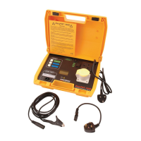
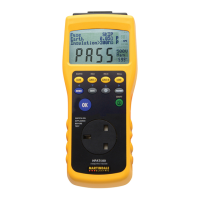
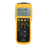
Figure 5.31: Examples of line impedance measurement result
Displayed results:
Z .............. line impedance
Isc ........... prospective short-circuit current
Lim .......... upper limit line impedance value
Prospective fault current I
PFC
is calculated from the measured impedance as follows:
factorscalingZ
U
I
LNL
N
PFC
_
)(
where:
Un ........................ Nominal U
L-N
or U
L1-L2
voltage (see table below),
Scaling factor ....... Impedance correction factor (see chapter 4.4.4 Z factor).