Martindale ET4000 / ET4500 Measurements
40
5.4.1 Contact voltage (RCD Uc)
A current flowing into the PE terminal causes a voltage drop on the earth resistance, i.e.
a voltage difference between the PE equipotential bonding circuit and earth. This
voltage difference is called contact voltage and is present on all accessible conductive
parts connected to the PE. It must always be lower than the conventional safety limit
voltage.
The contact voltage is measured with a test current lower than ½ I
N
to avoid trip-out of
the RCD and then normalized to the rated I
N
.
Contact voltage measurement procedure
Select the RCD function using the function selector switch.
Set sub-function to Uc using UP / DOWN keys.
Set test parameters (if required).
Connect the test leads to the instrument.
Connect the test leads to the wiring of the RCD to be tested (see Figure 5.19).
Press the TEST key to perform the measurement.
Store the result, if required, by pressing the MEM key (ET4500 only).
The contact voltage result relates to the rated nominal residual current of the RCD and
is multiplied by an appropriate factor (depending on RCD type and type of test current).
The 1.05 factor is applied to give a margin of error to take tolerances into consideration.
See Table 5.1 for detailed contact voltage calculation factors.
RCD type
Contact voltage Uc
proportional to
Rated I
N
AC
1.05I
N
Table 5.1: Relationship between Uc and I
N
Loop resistance is indicative and calculated from the Uc result (without additional
proportional factors) as follows:
N
C
L
I
U
R
.
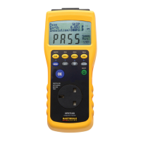
Figure 5.20: Example of contact voltage measurement results
Displayed results:
Uc................ contact voltage
Rl................. fault loop resistance
Rmax .......... Maximum earth fault loop resistance value according to BS 7671