Martindale ET4000 / ET4500 Measurements
46
Fault loop impedance measurement procedure
Select the Zloop function using the function selector switch.
Set sub-function to Zloop or Zs rcd using UP / DOWN keys.
Select test parameters (optional).
Connect the test leads to the instrument.
Connect the test leads to the installation wiring to be tested (see Figure 5.19 and
Figure 5.26).
Press the TEST key to perform the measurement.
Store the result, if required, by pressing the MEM key (ET4500 only).
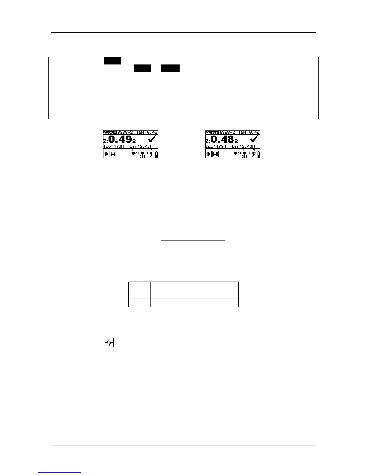
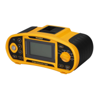
Figure 5.27: Examples of loop impedance measurement result
Displayed results:
Z .............. fault loop impedance
Isc ........... prospective fault current
Lim .......... upper limit fault loop impedance value
Prospective fault current I
PFC
is calculated from the measured impedance as follows:
factorscalingZ
U
I
PEL
N
PFC
_
where:
Un ........................ Nominal U
L-PE
voltage (see table below),
Scaling factor.......Impedance correction factor (see chapter 4.4.4 Z factor).
U
n
Input voltage range (L-PE)
110 V
(93 V U
L-PE
134 V)
230 V
(185 V U
L-PE
266 V)
Testing considerations
Large fluctuations of mains voltage can influence the measurement results (the
noise sign is displayed in the message field). In this case it is recommended
that the measurements are repeated a few times to check if the readings are
stable.
The Zloop measurement will trip-out the RCD in RCD-protected electrical
installations.
Select the Zs rcd (non-trip) measurement to prevent trip-out of RCD's in RCD
protected installations.
The measurement of fault loop impedance using the Zs rcd (non-trip) function
does not normally trip an RCD. However, the trip limit may be exceeded if a