14 Chapter 1: Introduction
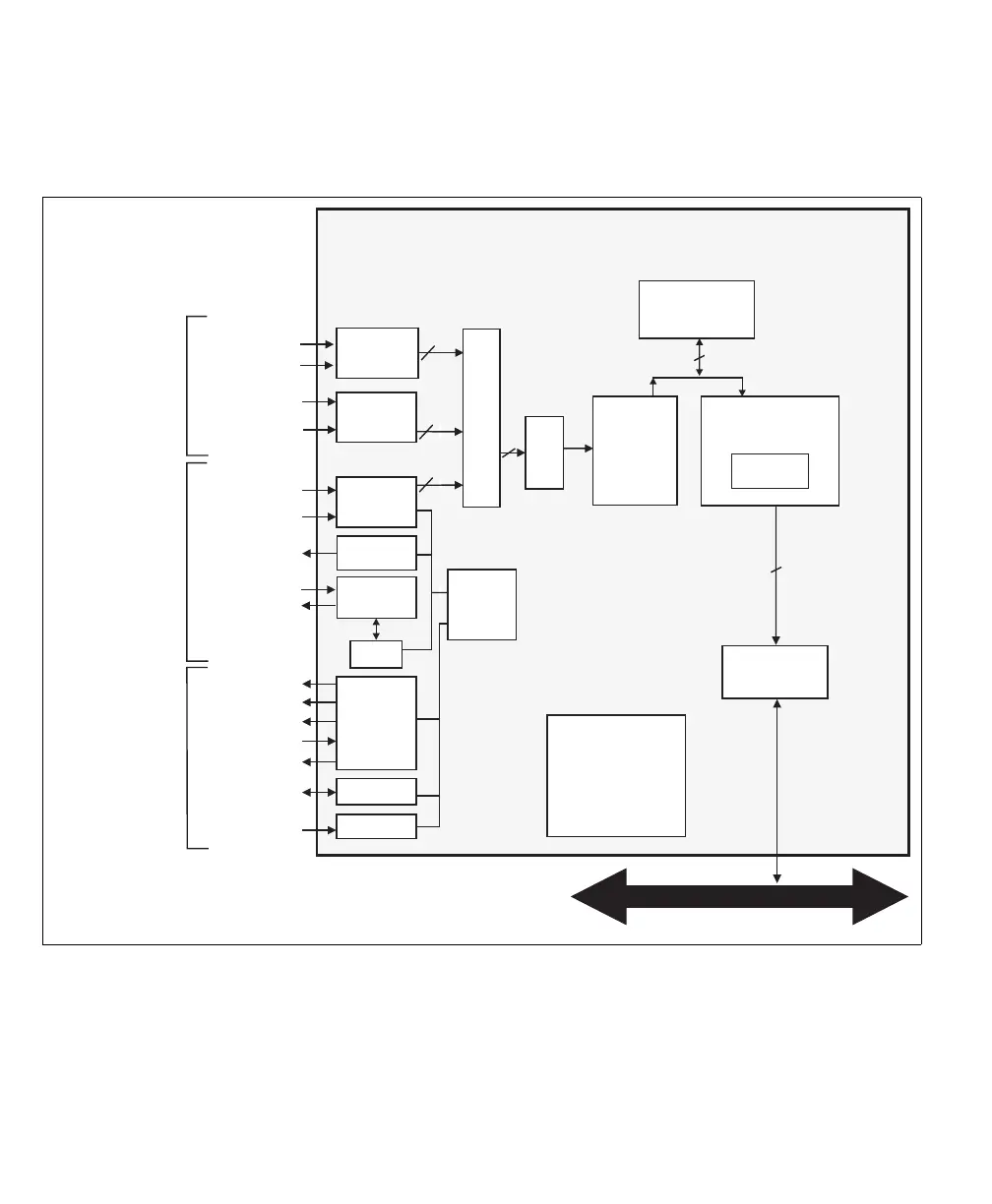
The following flow diagram shows Matrox Solios eV-CLFL in single-Medium and
single-Full configuration.
PSG
ChannelLink
Receiver #1
Clock
Data (24)
& Syncs (4)*
SerTFG
SerTC
24
UART
LVDS
drivers
and
receivers
OptoAux (4)
TTL buffers
On a separate bracket.
Aux In (4)
Aux Out (2)
HSYNC Out (1)
VSYNC Out (1)
Clock Out (1)
Optocoupler
Aux I/Os (4)
ChannelLink
Receiver #2
Clock
28
Cam Ctrl (4)
LVDS
drivers
LVDS driver
& receiver
32 DDR2
(up to 1.73 GB/s)***
64
(up to 860 MB/s)
PCI-X to PCIe
Bridge
Host PCIe bus
LUTs
64
Demultiplexer
Matrox Solios eV-CLFL
Acquisition
memory
(128/256/512 MB)
28 bits serialized across 4 LVDS pairs. In single-Medium mode,
ChannelLink Receiver #2 can only receive 24 bits of data and
ChannelLink Receiver #3 is not used.
*
**
x4 PCIe
(Up to 1 GB/s)
Camera Link
connector 1
(MDR-26)
Camera Link
connector 0
(MDR-26)
External Auxiliary
I/O connectors
(DBHD-44 and DB-9)
**
Acquisition
Controller
Video
Formatter
Color space
converter
MIL license
fingerprint
and
Supplemental MIL
license storage
ChannelLink
Receiver #3
Data (28)*
Data (28)*
Clock
28