Connectors on Matrox Solios eV-CLB and eV-CLF boards 83
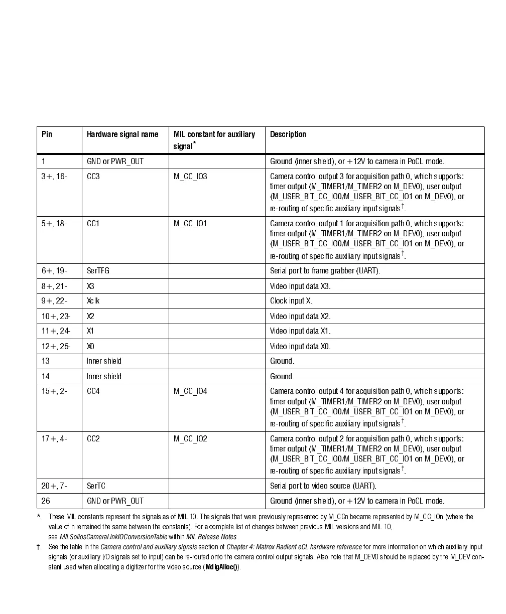
For Matrox Solios eV-CLB in dual-Base configuration, the two Camera Link video
input connectors have the same pinout; this pinout is listed in the following table.
Note that, in dual-Base configuration, each connector supports video input from
a different video source.
Pin Hardware signal name MIL constant for auxiliary
signal
*
Description
1 GND or PWR_OUT Ground (inner shield), or +12V to camera in PoCL mode.
3+, 16- CC3 M_CC_IO3 Camera control output 3 for acquisition path 0, which supports:
timer output (M_TIMER1/M_TIMER2 on M_DEV0), user output
(M_USER_BIT_CC_IO0/M_USER_BIT_CC_IO1 on M_DEV0), or
re-routing of specific auxiliary input signals
†
.
5+, 18- CC1 M_CC_IO1 Camera control output 1 for acquisition path 0, which supports:
timer output (M_TIMER1/M_TIMER2 on M_DEV0), user output
(M_USER_BIT_CC_IO0/M_USER_BIT_CC_IO1 on M_DEV0), or
re-routing of specific auxiliary input signals
†
.
6+, 19- SerTFG Serial port to frame grabber (UART).
8+, 21- X3 Video input data X3.
9+, 22- Xclk Clock input X.
10+, 23- X2 Video input data X2.
11+, 24- X1 Video input data X1.
12+, 25- X0 Video input data X0.
13 Inner shield Ground.
14 Inner shield Ground.
15+, 2- CC4 M_CC_IO4 Camera control output 4 for acquisition path 0, which supports:
timer output (M_TIMER1/M_TIMER2 on M_DEV0), user output
(M_USER_BIT_CC_IO0/M_USER_BIT_CC_IO1 on M_DEV0), or
re-routing of specific auxiliary input signals
†
.
17+, 4- CC2 M_CC_IO2 Camera control output 2 for acquisition path 0, which supports:
timer output (M_TIMER1/M_TIMER2 on M_DEV0), user output
(M_USER_BIT_CC_IO0/M_USER_BIT_CC_IO1 on M_DEV0), or
re-routing of specific auxiliary input signals
†
.
20+, 7- SerTC Serial port to video source (UART).
26 GND or PWR_OUT Ground (inner shield), or +12V to camera in PoCL mode.
*. These MIL constants represent the signals as of MIL 10. T he signals that were previously represented by M_CCn became represented by M_CC_IOn (where the
value of n remained the same betw een the co nstants). For a complete list of changes between previous MIL versions and MIL 10,
see
MILSoliosCameraLinkIOConversionTable
within
MIL Release Notes
.
†. See the table in the
Camera control and auxiliary signals
section of
Chapter 4: Matrox Radient eCL hardware reference
for more information on which auxiliary input
signals (or auxiliary I/O signals set to input) can be re-routed onto the camera control output signals. Also note that M_DEV0 should be replaced by the M _DEV con-
stant used when allocating a digitizer for the video source (
MdigAlloc()
).