84 Appendix B: Technical information
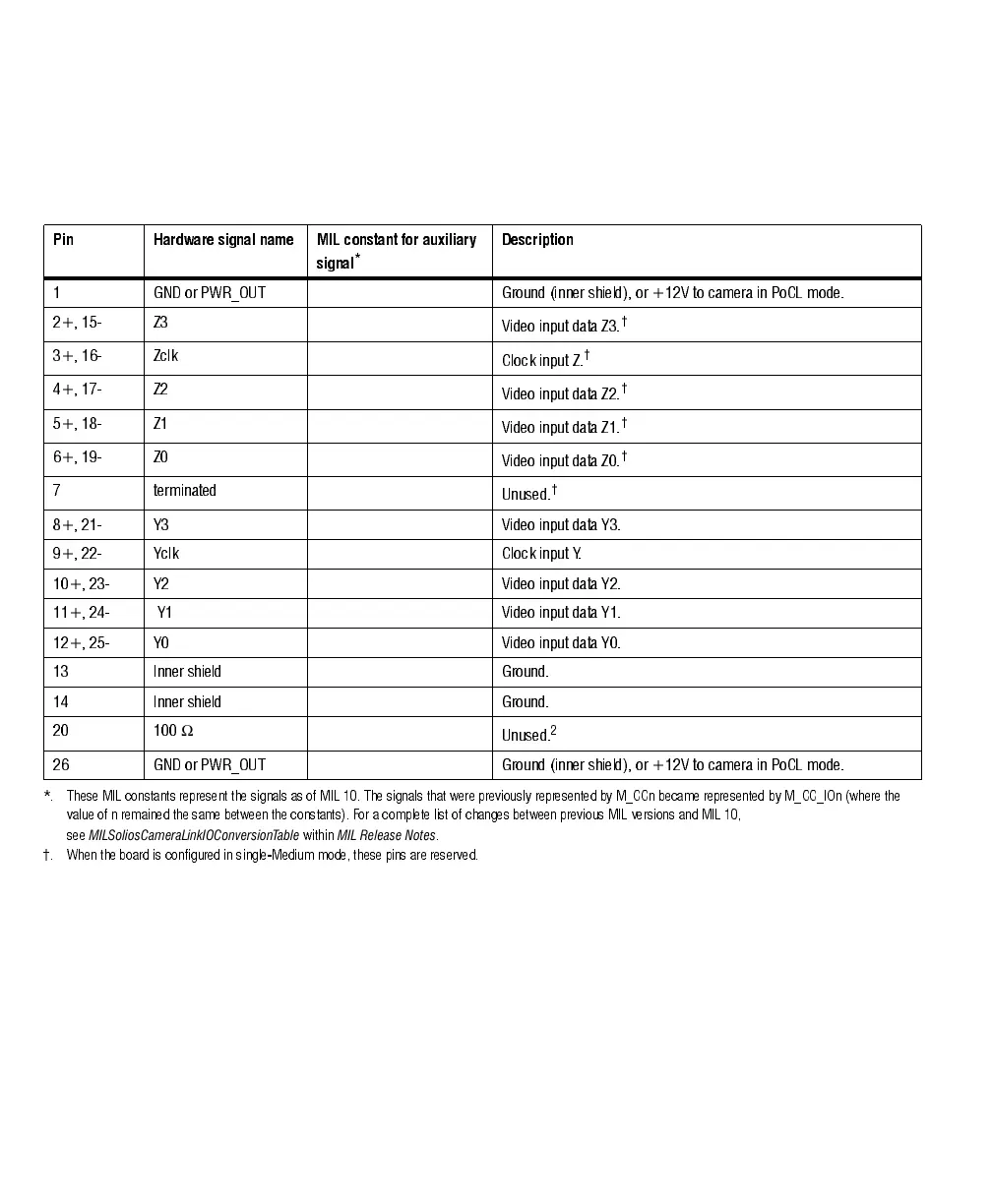
For Matrox Solios eV-CLB in single-Medium configuration and Matrox Solios
eV-CLF, the first connector has the pinout described above, while the second
connector has the following pinout.
To interface with the above connectors, use a standard Camera Link cable with a
26-pin high-density male mini Camera Link connector (HDR or SDR) at one
end. You can purchase such a cable from your video source manufacturer,
Components Express inc., 3M Interconnect Solutions for Factory Automation,
Intercon 1, or other third parties. Note that this cable is not available from Matrox.
❖ If using both Camera Link connectors to connect to the same video source
(single-Medium mode or single-Full mode), the cables you choose must be of the
same type and length. Otherwise, the cables can have different propagation delays.
Pin Hardware signal name MIL constant for auxiliary
signal
*
Description
1 GND or PWR_OUT Ground (inner shield), or +12V to camera in PoCL mode.
2+, 15 - Z3
Video input data Z3.
†
3+, 16 - Zcl k
Clock input Z.
†
4+, 17 - Z2
Video input data Z2.
†
5+, 18 - Z1
Video input data Z1.
†
6+, 19 - Z0
Video input data Z0.
†
7 terminated
Unused.
†
8+, 21- Y3 Video input data Y3.
9+, 22- Yclk Clock input Y.
10+, 23- Y2 Video input data Y2.
11+, 24- Y1 Video input data Y1.
12+, 25- Y0 Video input data Y0.
13 Inner shiel d Ground.
14 Inner shiel d Ground.
20 100
Ω
Unused.
2
26 GND or PWR_OUT Ground (inner shield), or +12V to camera in PoCL mode.
*. These MIL constants represent the signals as of M IL 10. The signals that were previously represented by M_CCn became represented by M_CC_IOn (where t he
value of n remained the same between the constants). For a complete list of changes between previous MIL versions and MIL 10,
see
MILSoliosCameraLinkIOConversionTable
within
MIL Release Notes
.
†. When the board is configured in single-Medium mode, these pins are reserved.