Home
Maxcess
Controller
Fife Polaris DP-20
Maxcess Fife Polaris DP-20 User Manual
4
of 1
of 1 rating
65 pages
Give review
Manual
Specs
To Next Page
To Next Page
To Previous Page
To Previous Page
Loading...
DP
-20 WEB GUI
DE CONTROL
LER USER MANUAL
www.maxcessintl.com
DP
-
20
MI 1-862 1 F
3
3-2
Setup Menu Chart
AUTOM
A
TIC M
ODE
1X.1
1X.2
1X.3
1X.4
Gain
Guide Point
Measurement
Exit Menus
SERVO-CENTER M
ODE
2X.1
2X.2
2X.3
2X.4
Servo-Center
Gain
Servo-Cen
ter
Guide Point
Measurement
Exit Menus
M
A
NUAL MO
DE
SELECT MENU
3X.1
3X.2
3X.3
3X.4
3X.5
3X.6
BASIC
SPECIAL
ADVANCED
LANGUAGE
CUSTOM
Exit Menus
BASIC
MENUS
3X.1.1
3X.1.2
3X.1.3
3X.1.4
3X.1.5
3X.1.6
3X.1.7
3X.1.8
3X.1.9
►
Gain
Guide Point
Guide
Polarity
Calibration
Auto Setup
Servo-Center
Gain
Servo-Cen
ter
Polarity
Measurement
Exit
Menus
SPECIA
L MENUS
3X.2.1
3X.2.2
3X.2.3
3X.2.4
3X.2.5
3X.2.6
3X.2.7
3X.2.8
3X.2.9
►
Deadband
Set Operation
Mode Enable
Set Sensor
Mode Enable
Set Jog
Enable
Set Jog
Polarity
Set
Jog Speed
Set
Sensor Type
LCD
Contrast
Exit
Menus
A
DV
AN
CED MENUS
3X.3.1
3X.3.2
3X.3.3
3X.3.4
3X.3.5
3X.3.6
3X.3.7
3X.3.8
3X.3.9
►
Restore
Settings
Backup
Settings
Set
Password
Set Output
A Delay
Set Output
B Delay
Loss of Null
Output Range
Digital I/O
(X3)
Test Signals
Exit
Menus
LANGUA
GE MENU
3X.4.1
►
Select
Language
CUSTOM MENU
S
3X.5.1
3X.5.2
3X.5.3
3X.5.4
►
ASC Control
Set ASC
Limits
Set ASC
Source
Exit Menus
MEASUR
EMENT SUB
MENUS
1X.3.1
2X.3.1
3X.1.8.1
1X.3.2
2X.3.2
3X.1.8.2
1X.3.3
2X.3.3
3X.1.8.3
1X.3.4
2X.3
.4
3X.1.8.4
1X.3.5
2X.3.5
3X.1.8.5
1X.3.6
2X.3.6
3X.1.8.6
1X.3.7
2X.3.7
3X.1.8.7
1X.3.8
2X.3.8
3X.1.8.8
1X.3.9
2X.3.9
3X.1.8.9
Sensor Signal
Edge L (X
5) or
Line C (X
4)
Sensor Signal
Edge R (X
4) or
Line E (X4)
Sensor Signal
Servo-Center
(X2)
Tach Signal
Motor
Type
Digital
Inputs
Firmware
Version
Serial
Number
Exit Menus
TEST SIGNA
LS
SUBMENUS
3X.3.8.1
3X.3.8.2
3X.3.8.3
3X.3.8.4
Sensor Current
Toggle
Outputs
Guide Test
Mode
Exit Menus
Notes:
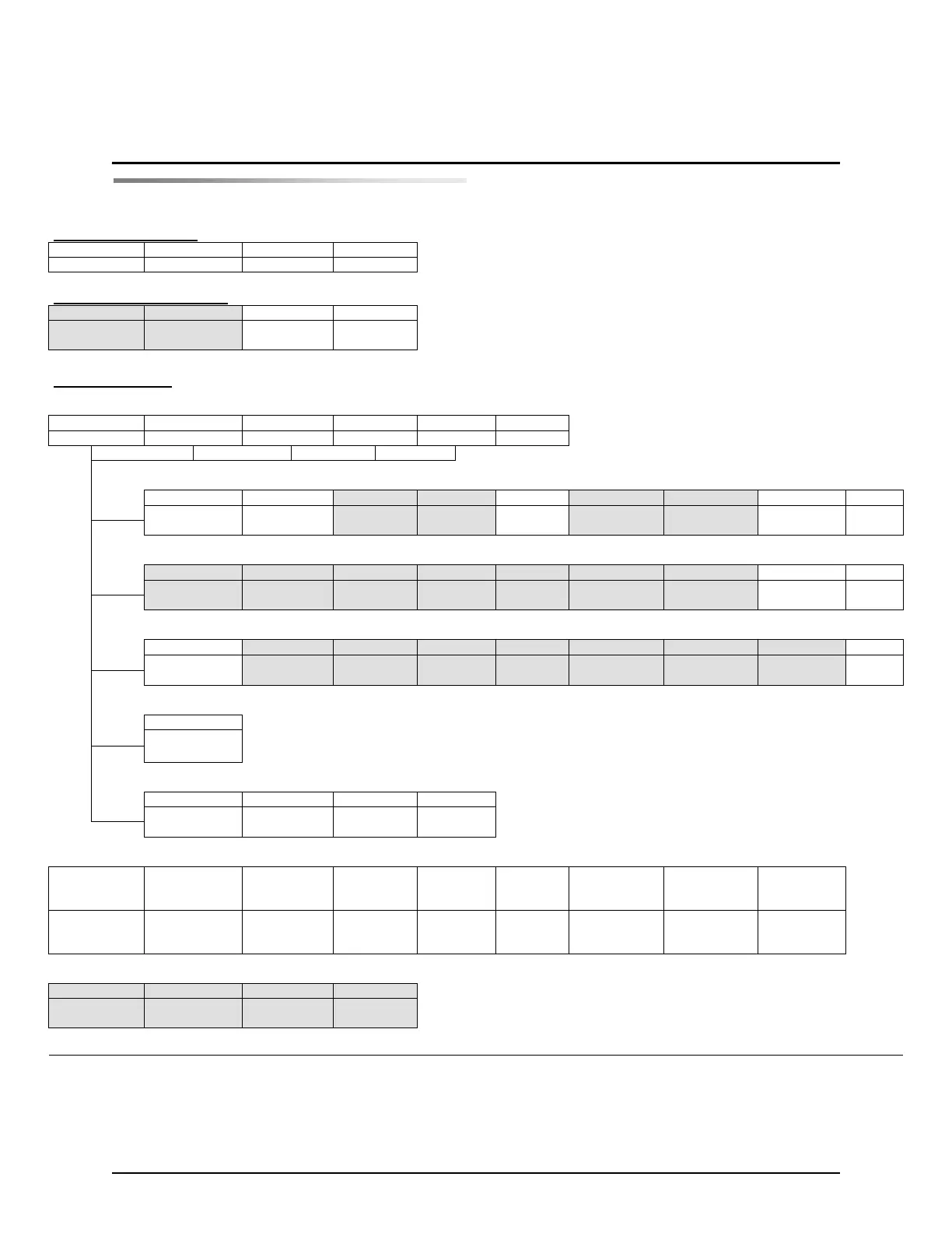
1.
The ‘X’ in the
Menu Number may
be A, B,
C, D, or E, depending on the sensor mode.
2.
The high
lighted menus are, by default, passw
ord protected if a password has been set.
3.
The text on the LCD Panel may vary slightly from the text in this chart.
11
13
Table of Contents
Table of Contents
3
General Introduction
5
General Information
5
Operator Interface
7
Function of the Operator Level Keys
7
Features of the LCD Panel
8
Setup Menu Structure
11
Setup Menu Notes
11
Setup Menu Chart
12
1, System Gain
13
2, System Guide Point
13
3, Measurement
14
1, Servo-Center Gain
17
2, Servo-Center Guide Point
17
3, Measurement
18
Basic Menus
21
1.1, System Gain
21
1.2, System Guide Point
21
1.3, Guide Polarity
22
1.4, Calibration, Edge Sensors
23
1.4, Calibration, Line Sensor, Center of Line Guiding
24
1.4, Calibration, Line Sensor, Edge of Line Guiding
25
1.4, Calibration, Servo-Center Sensor
27
1.5, Auto Setup
28
1.6, Servo-Center Gain
29
1.7, Servo-Center Polarity
30
1.8, Measurement
31
Special Menus
32
2.1, Deadband
32
2.2, Set Operation Mode Enable
33
2.3, Set Sensor Mode Enable, Edge Sensors
34
2.3, Set Sensor Mode Enable, Line Sensor
35
2.4, Set Jog Enable
36
2.5, Set Jog Polarity
37
2.6, Set Jog Speed
38
2.7, Set Sensor Type
39
2.8, LCD Contrast
40
Resetting the LCD CONTRAST to the Default
40
Advanced Menus
41
3.1, Restore Settings
41
3.2, Backup Settings
41
3.3, Set Password, Enter Password
42
3.3, Set Password, Delete Password
43
3.3, Set Password, Change Password
44
3.4, Set Output a Delay
45
3.5, Set Output B Delay
46
3.6, Set Loss of Null Output Range
47
3.7, Digital I/O, Enable/Disable
48
3.8.1, Test Signals, Sensor Current
48
3.8.2, Test Signals, Toggle Outputs
49
3.8.3, Test Signals, Guide Test Mode
50
Language Menu
52
4.1, Select Language
52
Custom Menus
53
5.1, ASC Control
53
5.2, Set ASC Limits
54
5.3, Set ASC Source
55
Parallel Matrix
56
Parallel Input Matrix
56
Parallel Output Matrix
56
System Notes
58
Troubleshooting
60
Fault Diagnostics - Fault Rectification
60
Fault Codes
61
Return Shipment Instructions
62
Motor/Valve List
63
Specifications
64
General
64
Inputs and Outputs
64
Certifications and Compatibility with Industrial Environments
65
Maximum Cable Lengths
65
Other manuals for Maxcess Fife Polaris DP-20
User Manual/Instructions
14 pages
4
Based on 1 rating
Ask a question
Give review
Questions and Answers:
Need help?
Do you have a question about the Maxcess Fife Polaris DP-20 and is the answer not in the manual?
Ask a question
Maxcess Fife Polaris DP-20 Specifications
General
Brand
Maxcess
Model
Fife Polaris DP-20
Category
Controller
Language
English
Related product manuals
Maxcess FIFE D-MAXE 2
95 pages
Maxcess D-MAXE
160 pages
Maxcess H6630EM
74 pages
Maxcess MAGPOWR CYGNUS-S3 Series
66 pages