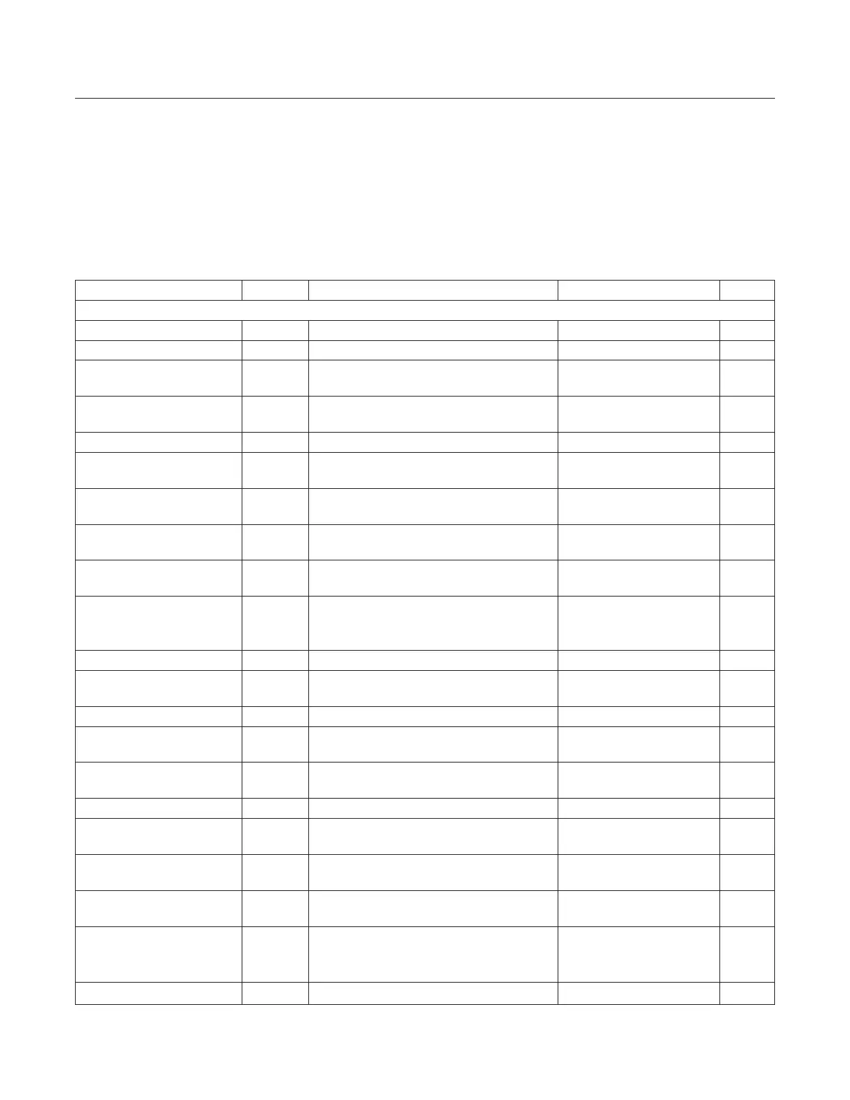
(MAX2771 EV kit, V
CC
= 2.7V to 3.3V, T
A
= -40°C to +85°C. Registers are set to the specified default states. LNA input is driven from
a 50Ω source. All RF measurements are done in the analog output mode with ADC bypassed. PGA gain is set to GAININ = 111010
through SPI interface, unless otherwise noted. Maximum IF output load is not to exceed 10kΩ||7.5pF on each pin. Typical values are
at V
CC
= 2.85V and T
A
= +25°C, unless otherwise noted. (Note 1))
PARAMETER SYMBOL CONDITIONS MIN TYP MAX UNITS
AC ELECTRICAL CHARACTERISTICS/ASCADED RF PERFORMANCE
RF Frequency L1 band 1575.42 MHz
RF Frequency - L2/L5 Band L2/L5 band 1227.6 MHz
Noise Figure
High band LNA input active, default mode
(Note 3)
1.4 dB
Noise Figure - L2/L5 Band
L2/L5 band (Note 6). Low-band LNA input
active, default mode (Note 3)
1.6 dB
Noise Figure Measured at the high-band mixer input 10.3 dB
Noise Figure - L2/L5 Band
L2/L5 band (Note 6). Measured at the
low-band mixer input
10.3 dB
Out-of-Band 3rd-Order Input
Intercept Point
Measured at the high-band mixer input
(Note 4)
-9 dBm
Out-of-Band 3rd-Order Input
Intercept Point - L2/L5 Band
L2/L5 band (Note 6). Measured at the
low-band mixer input (Note 4)
-9 dBm
In-Band Mixer Input Referred
1dB Compression Point
Measured at the high-band mixer input -85 dBm
In-Band Mixer Input Referred
1dB Compression Point –
L2/L5 Band
L2/L5 band (Note 6). Measured at the
low-band mixer input
-85 dBm
Mixer Input Return Loss Measured at high-band mixer input 10 dB
Mixer Input Return Loss -
L2/L5 Band
Measured at low-band mixer input 8 dB
Image Rejection 25 dB
Image Rejection -
L2/L5 Band
L2/L5 band (Note 6) 25 dB
Spurs at High-Band
LNA Input
LO leakage -101 dBm
Spurs at Low-Band LNA Input L2/L5 band (Note 6). LO leakage -101 dBm
Spurs at High-Band LNA
Input
Reference harmonics leakage -103 dBm
Spurs at Low-Band LNA Input
L2/L5 band (Note 6). Reference harmonics
leakage
-103 dBm
Maximum Voltage Gain
Measured from the high-band mixer input to
the baseband analog output
89 96 104 dB
Maximum Voltage Gain -
L2/L5 Band
L2/L5 band (Note 6). Measured from the
low-band mixer input to the baseband
analog output
89 96 104 dB
Variable Gain Range Measured at high-band mixer input 53 59 dB
Electrical Characteristics (continued)
www.maximintegrated.com
Maxim Integrated
│
7
MAX2771 Multiband Universal GNSS Receiver