(MAX2771 EV kit, V
CC
= 2.7V to 3.3V, T
A
= -40°C to +85°C. Registers are set to the specified default states. LNA input is driven from
a 50Ω source. All RF measurements are done in the analog output mode with ADC bypassed. PGA gain is set to GAININ = 111010
through SPI interface, unless otherwise noted. Maximum IF output load is not to exceed 10kΩ||7.5pF on each pin. Typical values are
at V
CC
= 2.85V and T
A
= +25°C, unless otherwise noted. (Note 1))
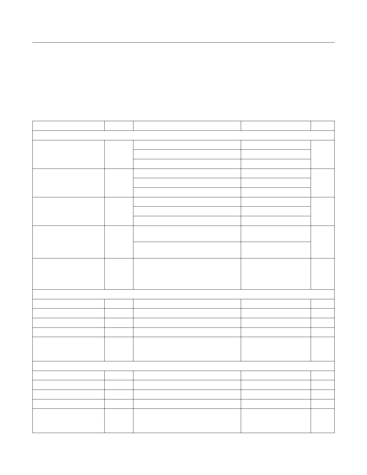
PARAMETER SYMBOL CONDITIONS MIN TYP MAX UNITS
AC ELECTRICAL CHARACTERISTICS/FILTER RESPONSE
Passband Center Frequency
FBW = 000, FCEN = 1011000 (Note 7) 3.9
MHzFBW = 010, FCEN = 1011000 (Note 7) 7.1
FBW = 001, FCEN = 1101001 (Note 7) 7.6
Passband 3dB Bandwidth
FBW = 000 (Note 7) 2.5
MHzFBW = 010 (Note 7) 4.2
FBW = 001 (Note 7) 8.7
Lowpass 3dB Bandwidth
FBW = 011, single-sided BW (Note 7) 11.7
MHzFBW = 111, single-sided BW (Note 7) 8.2
FBW = 100, single-sided BW (Note 7) 18
Stopband Attenuation
3rd-order lter, bandwidth = 2.5MHz,
measured at 4MHz oset (Note 7)
30
dB
5th-order lter, bandwidth = 2.5MHz,
measured at 4MHz oset (Note 7)
50
Passband Flatness
FBW = 001, Filter center frequency =
8.9MHz, 5th-order BPF, |response
magnitude at 5.1MHz - response magnitude
at 11.6MHz| (Note 7)
3 dB
AC ELECTRICAL CHARACTERISTICS/HIGH-BAND LNA
Power Gain 18 dB
Noise Figure 0.9 dB
Input IP3 (Note 5) -1.1 dBm
Output Return Loss 10 dB
Input Return Loss
With external matching circuit components
of 5.6nH series inductor and 1.7pF shunt
capacitor.
10 dB
AC ELECTRICAL CHARACTERISTICS/LOW-BAND LNA
Power Gain 18 dB
Noise Figure 0.9 dB
Input IP3 (Note 5) -1.1 dBm
Output Return Loss 10 dB
Input Return Loss
With external matching circuit components
of 8.4nH series inductor and 1.1pF shunt
capacitor.
8 dB
Electrical Characteristics (continued)
www.maximintegrated.com
Maxim Integrated
│
8
MAX2771 Multiband Universal GNSS Receiver