Setup
Connections
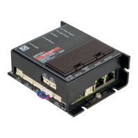
EPOS4 Disk 60/8 Hardware Reference
CCMC | 2021-10 | rel10276
3-21
3.3.1 Power & Logic Supply (X1/X2)
Basically, any power supply may be used provided that it meets the stated minimum requirements. A sepa-
rately sourced logic supply is optional.
Danger of confusion
Note that both connectors X1/X2 (Power & Logic Supply) and X3 (Motor) are of identical type. Make
sure not to interchange them.
Best practice
Keep the motor mechanically disconnected during the setup and adjustment phase.
Figure 3-8 Power and logic supply combo connector X1/X2
Table 3-12 Power and logic supply combo connector X1/X2 – Pin assignment
Table 3-13 Power and logic supply combo connector X1/X2 – Specifications
Continued on next page.
X1/X2
Pin
Signal Description
1 GND Ground
2
+V
CC
Power supply voltage (+12…+60 VDC)
3
+V
C
Logic supply voltage (+12…+60 VDC)
Combo Connector X1/X2
Suitable cable Power & Motor Cable on page 3-40
Suitable plug
Housing Molex Micro-Fit (0436450300)
Contact Molex Micro-Fit (0430300038)