Setup
Connections
EPOS4 Disk 60/8 Hardware Reference
3-36 CCMC | 2021-10 | rel10276
3.3.9 CAN IN (X14) & CAN OUT (X15)
The Disk CAN is specially designed being commanded and controlled via a Controller Area Network (CAN).
It is preferably used as a slave node in the CANopen network.
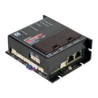
Figure 3-27 CAN 1 connector X14 / CAN 2 connector X15
Table 3-42 CAN 1 connector X14 / CAN 2 connector X15 – Pin assignment
Table 3-43 CAN 1 connector X14 / CAN 2 connector X15 – Specifications
Continued on next page.
X14
X15
Pin
Signal Description
1 CAN high CAN high bus line
2 CAN low CAN low bus line
3 — not connected
4 — not connected
5 — not connected
6 CAN V+ CAN external supply (device-internally not in use)
7 GND Ground
8 — not connected
9 — not connected
10 — not connected
— Shield Cable shield
Connector X14; X15
Suitable cables
CAN-CAN Cable on page 3-42
CAN-COM Cable on page 3-43
Suitable plugs
maxon (751388) (Table 3-10) or
HARTING (09 45 181 9002 XL) or Hirose (IX30G-B-10S-CV(7.0))