11921 Slauson Ave. Santa Fe Springs, CA. 90670 (800) 227-4116 FAX (888) 771-7713
19
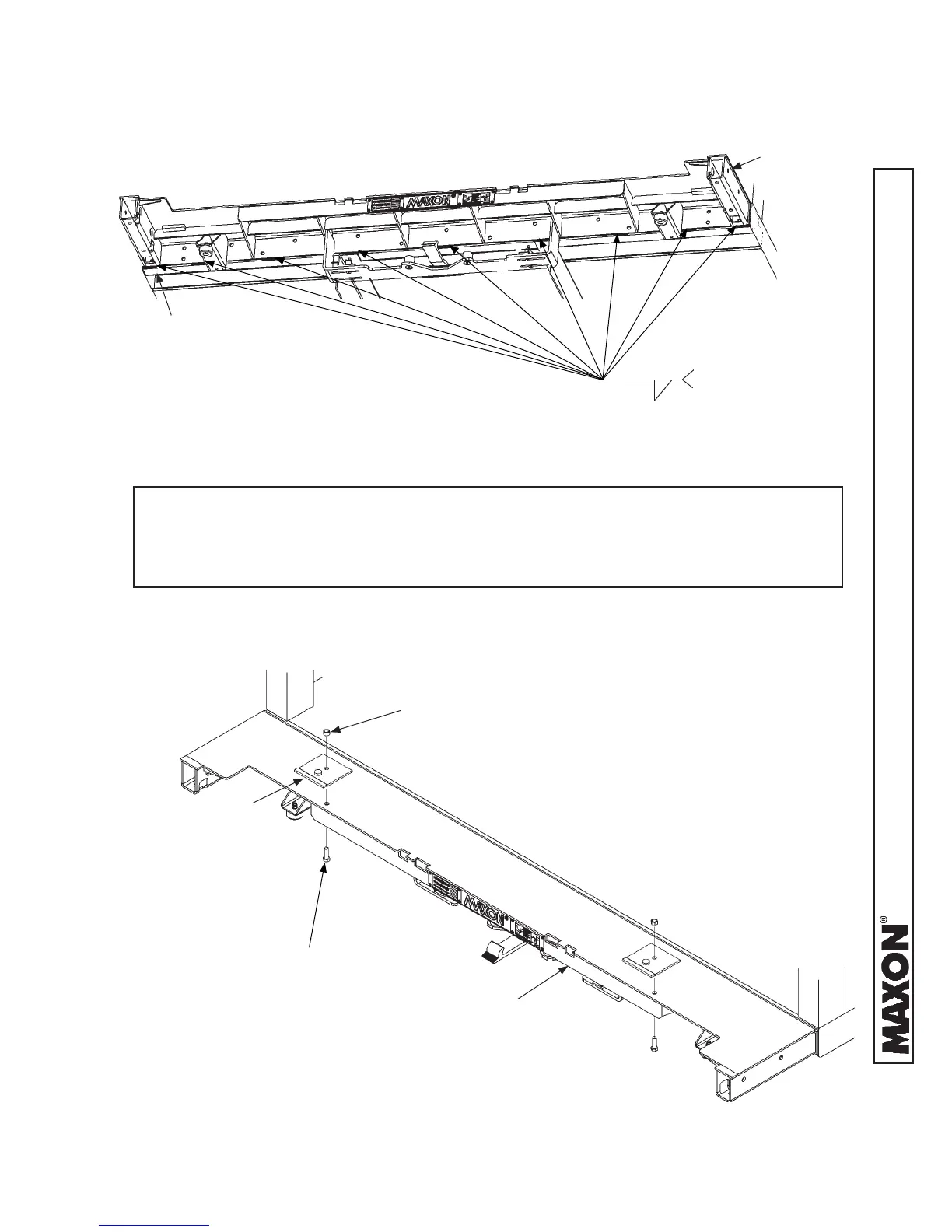
EXTENSION
PLATE
BRACKET
(2 PLACES)
BOLTING ON INSTALLATION BRACKETS
FIG. 19-2
CAP SCREW
1/2”-13 X 1-1/2” LG.
(2 PLACES)
HEX NUT
1/2”-13
(2 PLACES)
2. Bolt 2 installation brackets (parts bag items) on the
extension plate as shown in FIG. 19-2. Tighten hex
nuts securely.
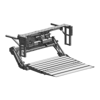
EXTENSION PLATE WELDS - VIEWED FROM UNDERNEATH
FIG. 19-1
EXTENSION
PLATE
3/16”
WELD LENGTH & SPACE:
2”- 11 3/4” ( 96”W VEHICLE)
2”- 12 1/2” (102”W VEHICLE)
VEHICLE
BODY
NOTE: During installation of liftgate, installation brackets keep the heel of the plat-
form level with extension plate and maintain a ¾” gap between extension
plate and heel of platform. The extension plate has bolt holes for bolting on
the installation brackets provided in parts box.
STEP 1 - ATTACH EXTENSION PLATE TO VEHICLE -
Continued
 Loading...