11921 Slauson Ave. Santa Fe Springs, CA. 90670 (800) 227-4116 FAX (888) 771-7713
42
1. Push control switch to UP position to pressurize hydraulic system. Listen for hydraulic
fl uid fl owing through the system. Check for fl uid leaks. When the sound of fl owing fl uid
stops, release control switch. Hydraulic system is ready.
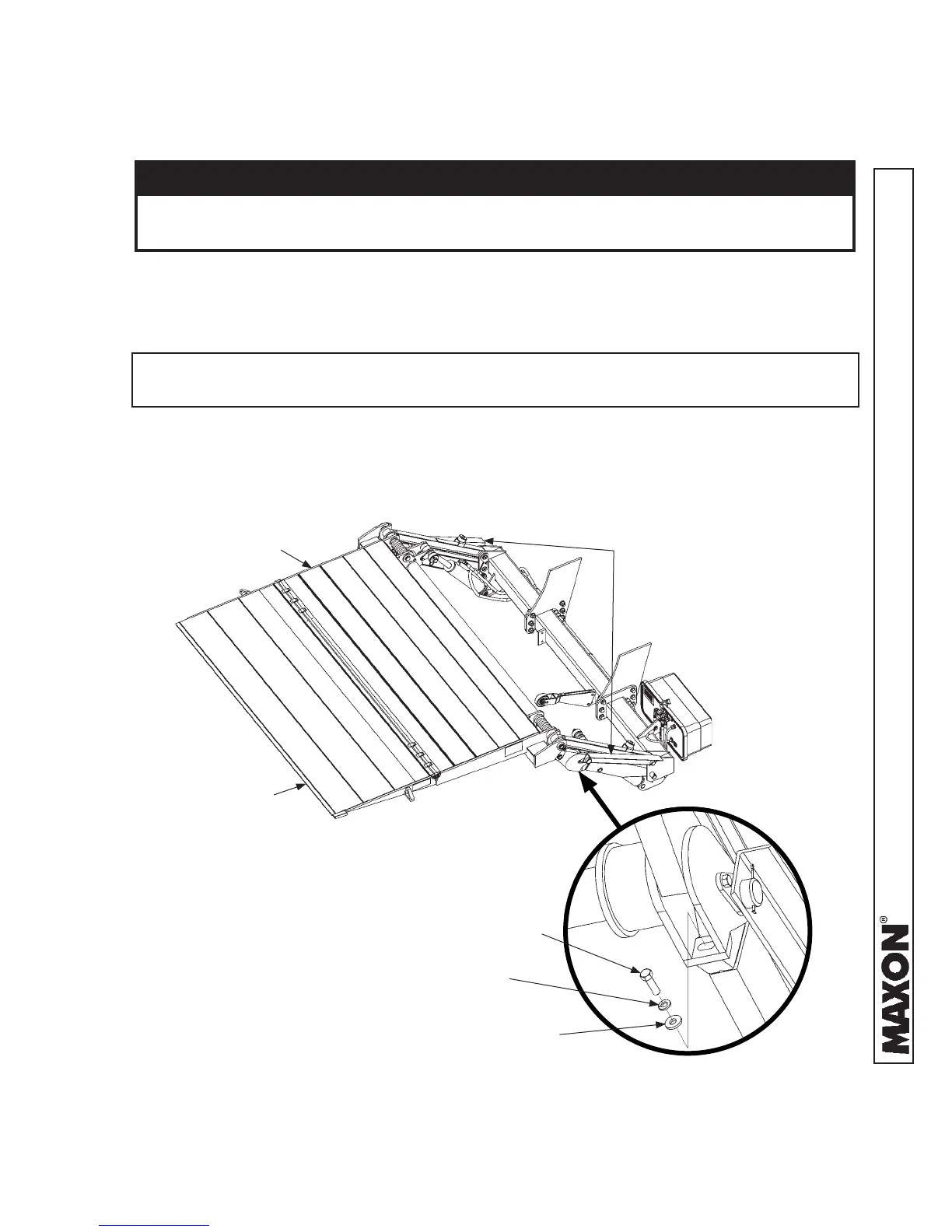
2. Remove locking angles from lift arms (FIG. 42-1A).
NOTE: To operate Liftgate, locking angles must be removed from the lift arms and
shipping bolt must be removed from both knuckles.
3. With platform open (FIG. 42-1A), unbolt each knuckle as shown in FIG. 42-1B.
CAUTION
Check for leaking hydraulic fl uid as the system is being pressurized. If there is
leakage, stop & correct the problem before fully pressurizing the system.
STEP 10 - REMOVE LOCKING ANGLES & KNUCKLE
BOLTS, CHECK FOR INTERFERENCE
FLIPOVER
PLATFORM
LOCKING
ANGLES
FIG. 42-1A
UNBOLTING KNUCKLE
FIG. 42-1B
BOLT
FLAT
WASHER
LOCK
WASHER
 Loading...