11921 Slauson Ave. Santa Fe Springs, CA. 90670 (800) 227-4116 FAX (888) 771-7713
36
STEP 6 - CONNECT GROUND CABLE (RECOMMENDED)
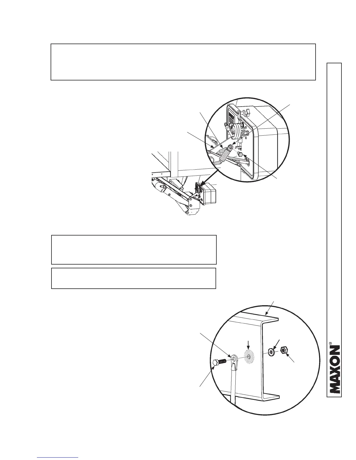
PUMP MOUNTING
BRACKET
CONNECTING EXTERNAL GROUND CABLE
FIG. 36-1
NOTE: To ensure power unit is correctly grounded, MAXON recommends
connecting 2 gauge ground cable from grounding connection on pump
mounting plate to a grounding point on the frame, or negative battery
terminal in the optional battery box.
1. Unbolt pump internal ground
cable from the pump mount-
ing bracket. Then, bolt and
tighten internal ground cable
and external ground cable
(parts box) to mounting
bracket (FIG. 36-1).
TERMINAL LUG
(EXTERNAL GROUND
CABLE)
NOTE: If there is a grounding point on the frame,
use it to connect ground cable. Then, skip
the step for drilling a hole.
2. Extend the ground cable to reach
vehicle frame (FIG. 36-2) without
putting tension on cable (after con-
nection). Connect to an existing
grounding point if available.
5. Bolt the ground cable terminal
lug to vehicle frame as shown in
FIG. 36-2.
NOTE: Clean the ground cable connection point
on the frame down to bare metal.
3. If necessary, drill a 11/32” (0.343”)
hole in vehicle frame for bolting
the ground cable terminal lug
(FIG. 36-2).
FIG. 36-2
TERMINAL LUG
(GROUND CABLE)
5/16"-18 X 1" LG
CAP SCREW
5/16” FLAT
WASHER
5/16”-18
LOCK NUT
VEHICLE CHASSIS
(TRUCK FRAME SHOWN)
BARE
METAL
4. To prevent corrosion, paint or
use galvanized spray on bare
metal area FIG. 36-2.
CAP SCREW
INTERNAL
GROUND
CABLE
 Loading...