11921 Slauson Ave. Santa Fe Springs, CA. 90670 (800) 227-4116 FAX (888) 771-7713
59
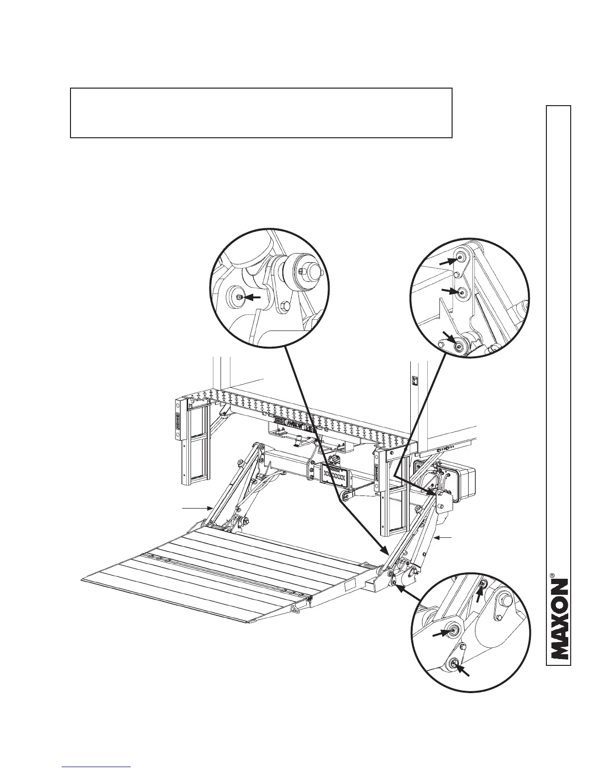
Refer to lubrication diagram (FIG. 59-1) to fi nd the
lube fi ttings on cylinders and arms. Pump EP chassis
grease in each lube fi tting on the cylinders and arms
until grease starts oozing from ends of the bearings.
Then, wipe off excess grease with a clean lint-free
cloth.
STEP 16 - LUBE GREASE FITTINGS AS NEEDED
LUBRICATION DIAGRAM
FIG. 59-1
NOTE: Lube fi ttings are shown for the RH cylinder, lift arm, and parallel
arm. There are also lube fi ttings at the same places on the LH
cylinder, lift arm, and parallel arm.
LH CYLINDER,
LIFT ARM &
PARALLEL ARM
RH CYLINDER,
LIFT ARM &
PARALLEL ARM
 Loading...