11921 Slauson Ave. Santa Fe Springs, CA. 90670 (800) 227-4116 FAX (888) 771-7713
33
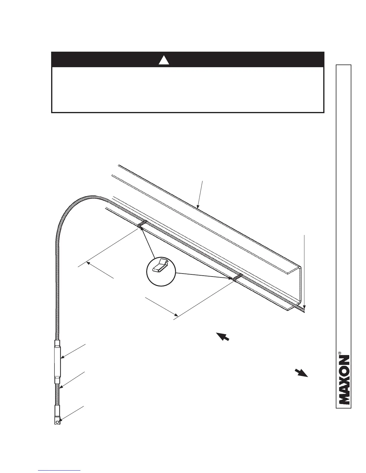
STEP 4 - RUN POWER CABLE - Continued
2. Clip fused power cable to vehicle chassis with fuse nearest
the vehicle battery, as shown in FIG. 33-1. Keep enough
cable near the battery to reach the positive terminal without
straining cable (after connection). Run cable to pump box
on Liftgate.
FIG. 33-1
Never route an energized wire. Make sure the vehicle battery is disconnected.
Always route electrical wires clear of moving parts, brake lines, sharp edges
and exhaust systems. Avoid making sharp bends in wiring. Attach securely.
If drilling is necessary, fi rst check behind the drilling surface so you do not
damage any fuel lines, vent lines, brake lines or wires.
CAUTION
175 AMP FUSE
SHORTEST
CABLE END
TERMINAL LUG
(TO VEHICLE BATTERY)
VEHICLE FRAME
(TRUCK FRAME SHOWN)
18” - 24”
SPACING
CHARGE LINE
(TO PUMP BOX)
FRONT OF VEHICLE
REAR OF VEHICLE
CABLE
CLIPS
!
 Loading...