11921 Slauson Ave. Santa Fe Springs, CA. 90670 (800) 227-4116 FAX (888) 771-7713
52
STEP 12 - ADJUST PLATFORM - Continued
LOWER PLATFORM
EDGE (OUTBOARD)
THIS DISTANCE (“B”)
GRIND METAL
FROM PLATFORM
STOP
1” 1/16”
2” 1/8”
3” 3/16”
4” 1/4”
TABLE 52-1
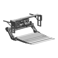
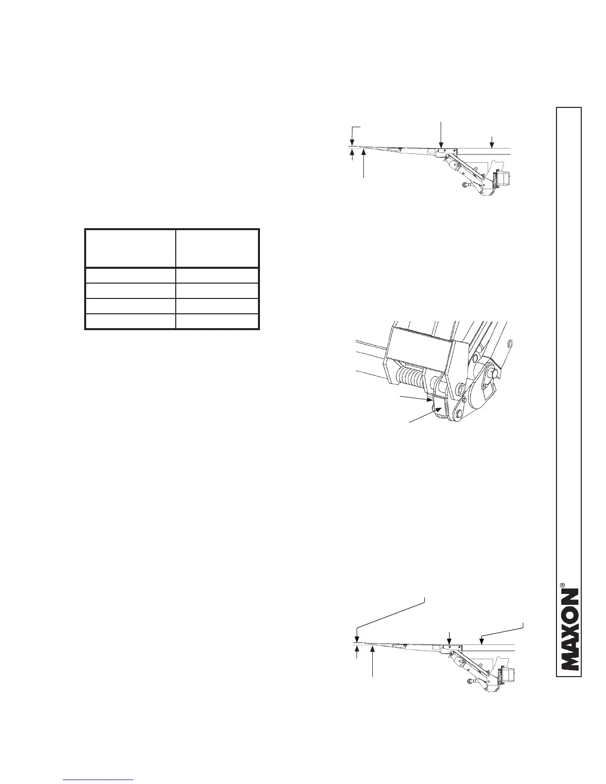
6. Lower the platform, then raise it to bed
level. The outboard edge of platform should
be level or up to 1” maximum above bed
level (FIG. 52-3).
4. Compare measurement “B” (FIG.
52-1) with the distances and grinding
depths in TABLE 52-1. For example:
If measurement “B” (FIG. 52-1) is 3”
above bed level and you want to lower
the outboard edge of platform to 1”
above bed level, grind 1/8” from each
platform stop (TABLE 52-1).
5. Grind metal from platform stops (FIG.
52-2) to lower outboard edge of plat-
form to correct position.
PLATFORM EDGE ABOVE BED LEVEL
FIG. 52-3
GRINDING PLATFORM STOPS
(CURBSIDE SHOWN)
FIG. 52-2
GRIND THIS FACE
(SEE TABLE 52-1)
SHACKLE
(REF)
PLATFORM EDGE ABOVE BED LEVEL
FIG. 52-1
LEVEL LINE
“B”
VEHICLE
FLOOR (REF)
EXTENSION
PLATE (REF)
LEVEL LINE
OUTBOARD EDGE
1” MAX (UP TO 53” BED HT.)
0” LEVEL (OVER 53” BED HT.)
VEHICLE
FLOOR (REF)
EXTENSION
PLATE (REF)
 Loading...