Rewinder RW500
93
Installation, commissioning
Making the stationary mains connection
7.3.5 Connecting the protective equipotential bonding conductor
The RFI filters of the frequency converters used generate a system-condi-
tioned grounding leakage current.
Since this can be greater than 10 mA, according to EN 60204-1 Clause
8.2.8 a protective equipotential bonding conductor is necessary.
This should have a cross-section of 10 mm
2
.
Procedure:
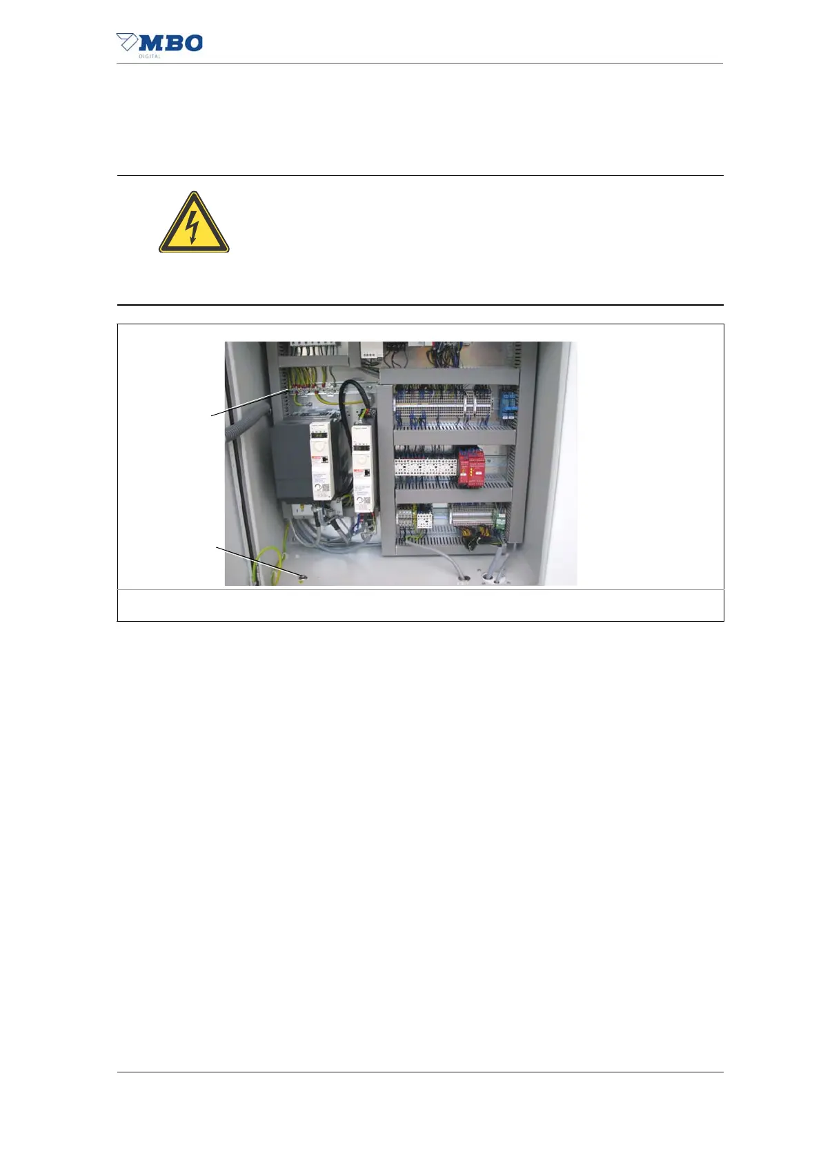
1) Insert the protective equipotential bonding conductor into the main
control cabinet through the cable grommet (1).
2) Connect the protective equipotential bonding conductor to the PE con-
nection terminal strip (2).
The protective equipotential bonding conductor is connected.
CAUTION
Discharge currents greater than 10 mA.
Non-observance could result in property damage.
• Connect the protective equipotential bonding conductor to the PE
terminals.
• Cross-section 10 mm
2
(Cu).
1 Cable grommet 2 PE connection terminal strip
Illustration 46: Connection of protective equipotential bonding conductor