Page 28 IM-738
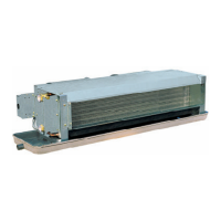
Figure 30. RFS/RCS 015-030 Refrigerant Piping Connections
Note: RFS units with front discharge do NOT include refrigerant piping to the DX coil. Field piping is required.
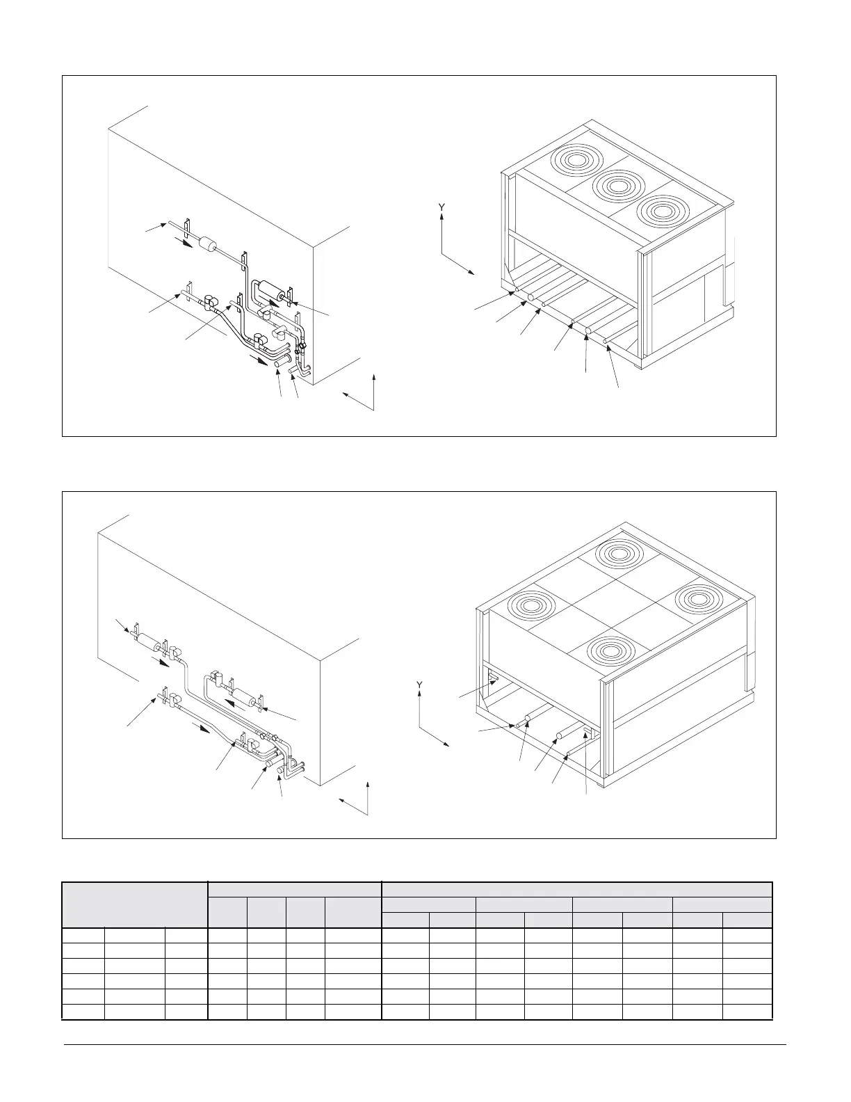
Figure 31. RFS/RCS 036 & 040 Refrigerant Piping Connections
Note: RFS units with front discharge do NOT include refrigerant piping to the DX coil. Field piping is required.
Table 7:
H G 1
H G 2
S 2
S 1
L 2
L 1
X
Y
L 1
H G 1
H G 2
S 2
S 1
X
L 2
Component Circuit
Connection Sizes Connection Locations
015C 020C 025C 030C- 040C
RFS/RFR 015-030 RCS 015-030 RFS/RFR 036 & 040 RCS 036 & 040
X (in.) Y (in.) X (in.) Y (in.) X (in.) Y (in.) X (in.) Y (in.)
S1 Suction Line Ckt.1 1-1/8 1-1/8 1-5/8 1-5/8 9.00 5.70 67.60 6.25 8.25 5.70 59.50 19.30
S2 Suction Line Ckt.2 1-3/8 1-5/8 1-3/8 1-5/8 14.00 5.70 28.00 6.25 13.25 5.70 34.60 19.30
L1 Liquid Line Ckt.1 5/8 5/8 7/8 7/8 56.00 32.00 75.00 6.25 79.00 25.00 70.50 25.00
L2 Liquid Line Ckt.2 7/8 7/8 7/8 7/8 7.60 28.00 21.00 6.25 15.00 25.00 23.50 25.00
HG1 HGBP Line Ckt.1 7/8 7/8 7/8 7/8 52.00 10.00 60.80 6.25 67.00 6.70 64.60 6.60
HG2 HGBP Line Ckt.2 7/8 7/8 7/8 7/8 36.00 16.00 35.50 6.25 32.00 6.70 29.50 6.00
L 1
H G 1
H G 2
S 2
S 1
X
L 2
L 1
H G 1
H G 2
S 2
S 1
X
L 2