OM Centrif Micro ΙΙ-5 75
Description
Auto Reset
96 CPU Error – Illegal Instruction Trap N
97 CPU Error – Software Watchdog Fault N
98 CPU Error – Spurious Interrupt N
99 CPU Error – Program Storage Fault N
NOTE: If a fault occurs that has a Y in the “Auto Reset” column, and P14 (Auto Fault Reset Time) is set to
some value other than OFF, then the fault will automatically be cleared after the time specified by P14.
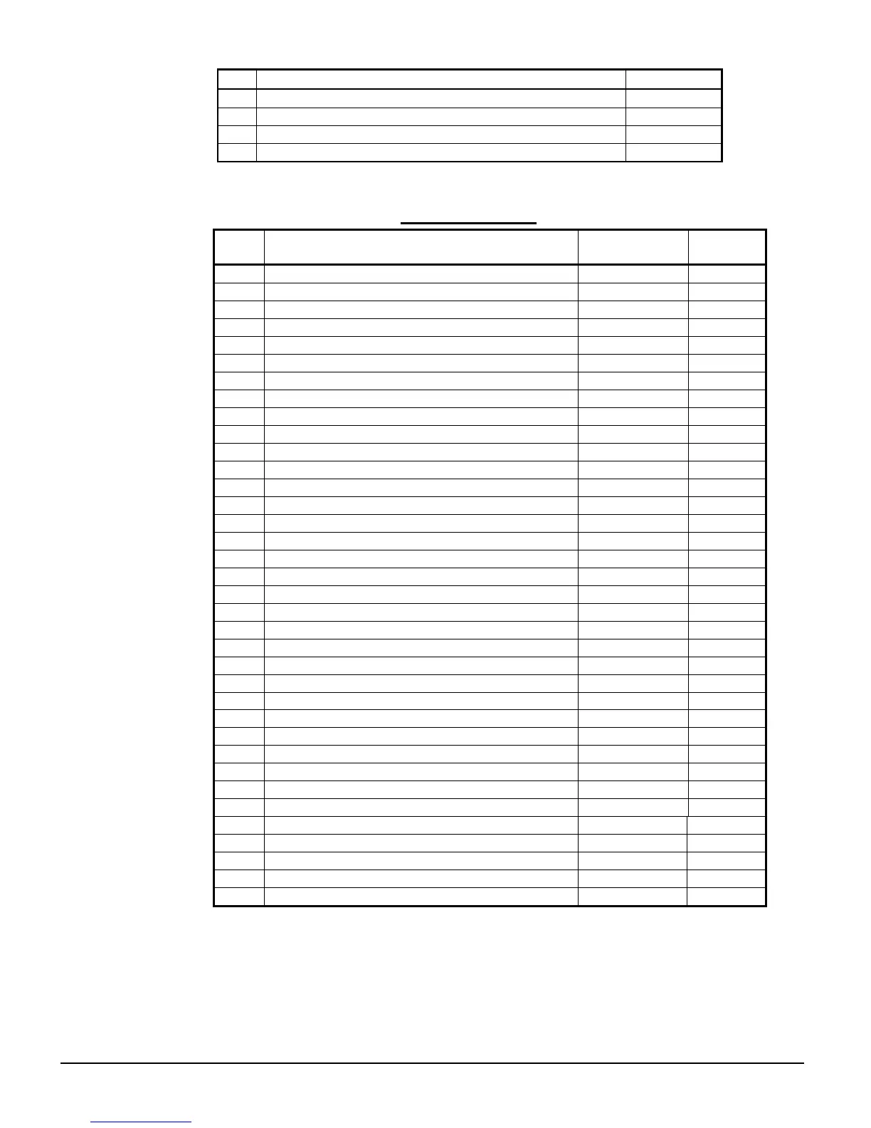
Table 31, Faults/Alarms, Solid State Starter
Description
Controlled
Stop
Auto
Reset
00 No fault
-
-
01 UTS (Up To Speed) Time Limit Expired Y Y
02 Motor Thermal Overload Trip Y N
10 Phase Rotation Error, not ABC N Y
12 Low Line Frequency N Y
13 High Line Frequency N Y
15 Input power not three phase N Y
21 Low Line L1-L2 Voltage Y Y
22 Low Line L2-L3 Voltage Y Y
23 Low Line L3-L1 Voltage Y Y
24 High Line L1-L2 Voltage Y Y
25 High Line L2-L3 Voltage Y Y
26 High Line L3-L1 Voltage Y Y
27 Phase Loss N Y
28 No Line Voltage N Y
30 I.O.C. (Instantaneous Overcurrent) N N
31 Overcurrent Y N
37 Current Imbalance Y Y
38 Ground Fault Y N
39 No Current at Run N Y
40 Shorted / Open SCR N N
41 Current While Stopped, Motor Failed To Stop N N
47 Stack Protection Fault (SCR at Operating Limit) N Y
48 Bypass Contactor Fault (on STOP input) Y N
50 Control Power Low N Y
51 Current Sensor Offset Error - N
52 Burden Switch Error N N
60 Thermistor Trip (on DIN#1, Motor Overheat Input) N N
61 Stack OT Switch Trip (on DIN#2) N N
71 Analog Input Trip (Not Used) Y Y
82 Modbus Timeout (Communication Fault) Y Y
95 CPU Error – Parameter Storage Fault N N
96 CPU Error – Illegal Instruction Trap N N
97 CPU Error – Software Watchdog Fault N N
98 CPU Error – Spurious Interrupt N N
99 CPU Error – Program Storage Fault N N
NOTES:.
1. If a fault occurs that has a Y in the “Controlled Stop” column, and P21 (Controlled Fault Stop) is set to
On, and P9 (Stop Mode) is set to dcL, then the starter will perform a voltage decel to stop. Otherwise it
will coast to stop.
2. If a fault occurs that has a Y in the “Auto Reset” column, and P22 (Auto Fault Reset Time) is set to some
value other than OFF, then the fault will automatically be cleared after the time specified by P22.
3. Manual reset is accomplished by pressing the reset button on the LED display. See Figure 38. A stack
over temperature fault (number 61) requires pressing the reset button located on the stack first.