October 2008 "2033ES / 2633ES" Service & Parts Manual - ANSI Specifications
Page 2-10
Tilt Alarm
The tilt sensor is located in the Base Control Box
Tilt Alarm Visual
A warning light provided at the platform console will
give a visual warning when the machine is at an
unsafe angle; Platform should not be elevated when
the warning indicator light is on.
Tilt Alarm Test
This can be tested by tipping the sensor. This “Push-
To-Test” feature enables tilt alarm to be tested with-
out losing its adjustment. Individually push down on
each of the three fastened corners of the tilt alarm.
There should be enough travel to cause the alarm to
sound as each corner is pressed. (There is approxi-
mately a 1-3 second delay). It the alarm does not
sound, the flange nuts have been tightened too far.
Loosen the nut on the 90° corners and repeat this
test procedure.
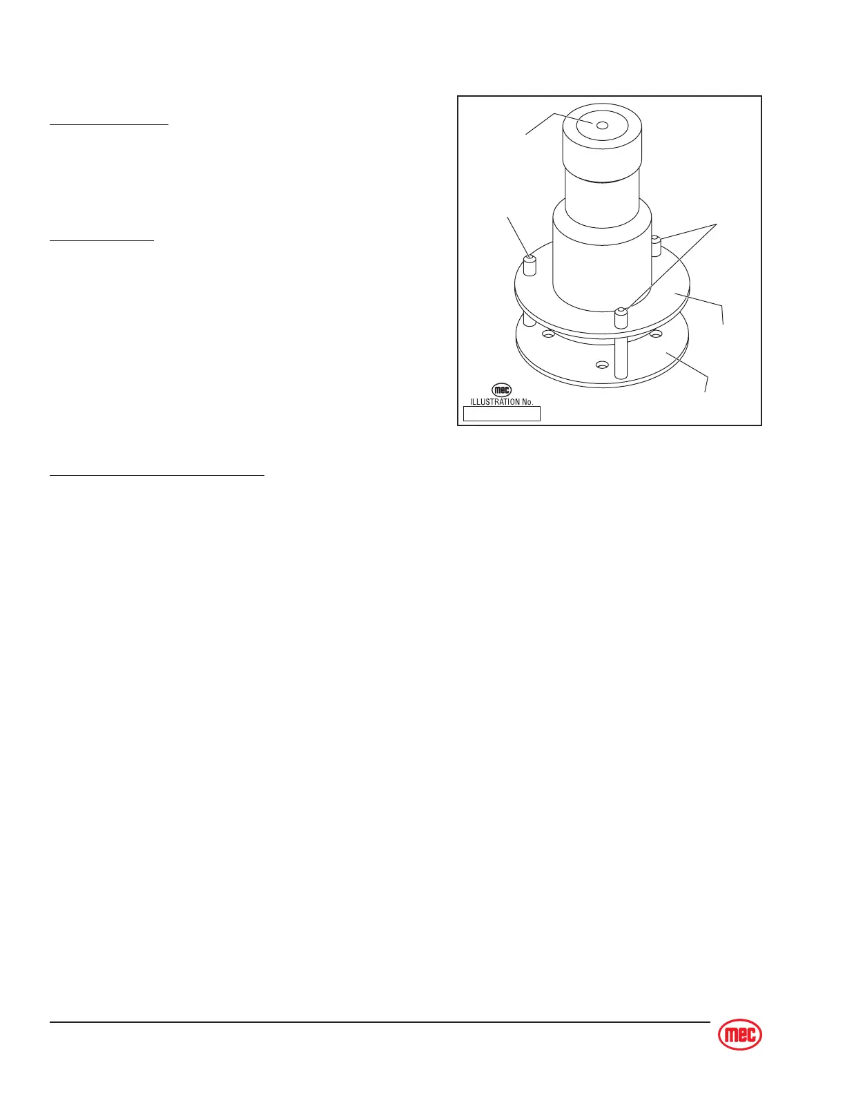
Tilt Alarm Sensor Adjustment
♦ Before attempting to adjust the alarm, park the machine on a firm, flat, level surface. Use
of an inclinometer is recommended to ensure front and rear of chassis is level.
♦ Open the base control panel to access the sensor. Adjust the three flange nuts until the
bubble on top of the sensor is centered.
♦ Check that the electrical connections are correct and secured tight.
♦ Close/shut the base control panel.
ART_2180
Flange nut
Tilt Base
Flange Nut
Level Bubble
Mounting Plate