8] Connect the breaker trip coil to EGIL trip coil
output.
9] Make sure a jumper is connected between
the trip coil input and the close coil input.
10] 10. Connect the auxiliary voltage plus (+) to
the coil input on EGIL.
11] Turn EGIL power switch on.
Select measurement method
1] Select MOTION from the ANALOG CHANNEL
menu.
2] Choose the measurement method.
If you use a rotating transducer or a linear transducer
that is not directly mounted on the moving contact,
select measure method STROKE LENGTH. Enter the
moving contact’s nominal stroke length and press
ENTER. For more information, see section 7.4 “Analog
Channel”.
If you use a linear transducer that is directly mounted
on moving contact, select measure method TRANSD
LENGTH. Enter the transducer’s length and press EN-
TER. If the exact length of the transducer is unknown,
you can find out what it is by calibrating the trans-
ducer. For more information, see section 7.4 “Analog
Channel”.
EGIL is now ready for motion measurement. Remember
that the first operation must be a single close or open
operation.
Connect the transducer
1] Connect the OUT terminal to one end of the
position transducer (potentiometer).
2] Connect the IN terminal to the slide of the
transducer.
3] Connect the 0 terminal to the other en of the
transducer.
4] The cable shield should not be grounded on
the transducer side.
Resistive
transducer
Moving slider
Cable
Screen
Input EGIL
OUT
IN
0
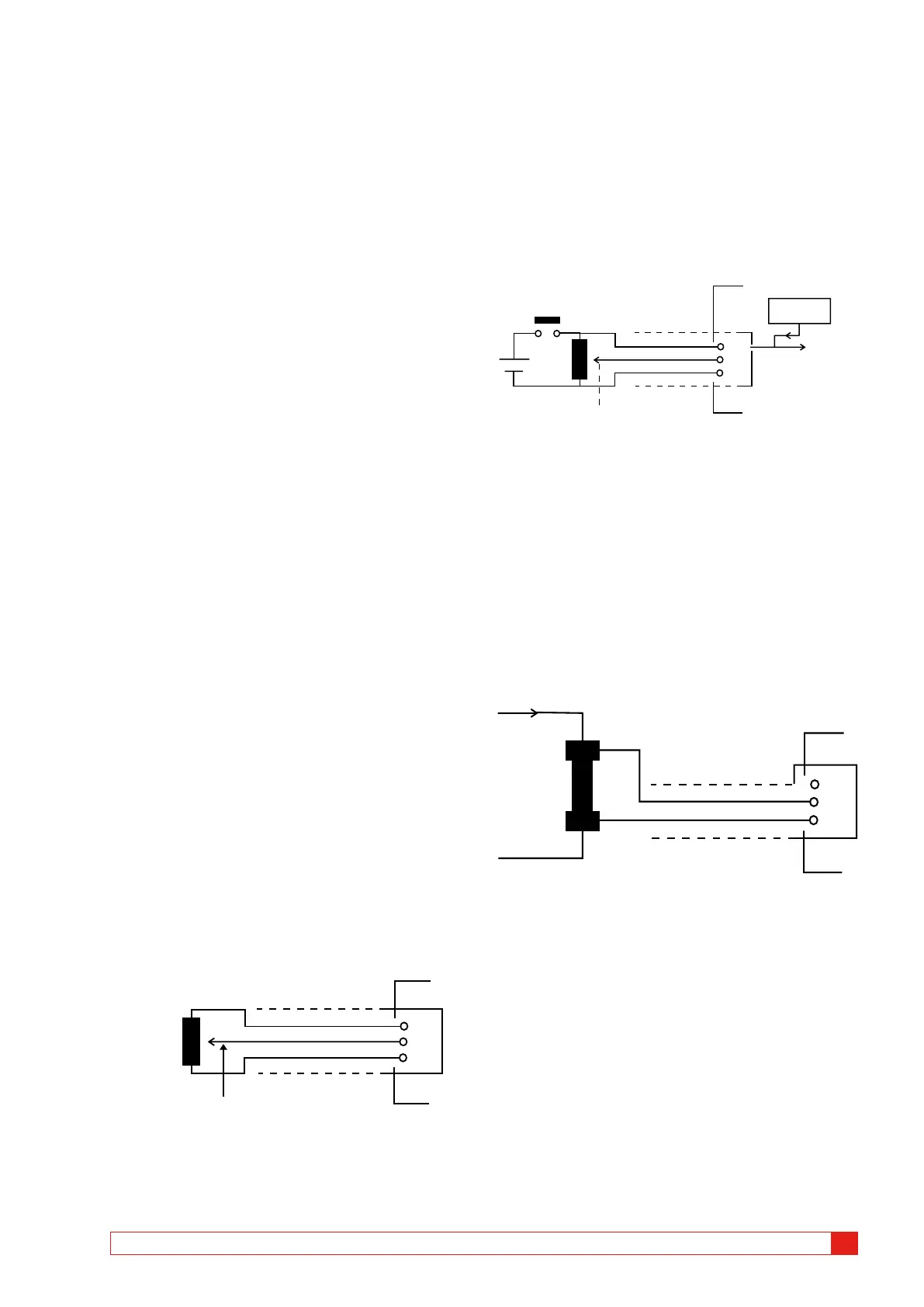
Resistive position transducer with very
low resistance
When the resistance is below 100 ohm, an external
power supply has to be used, e.g. two torch (flash-
light) batteries in series. Connect them across the
transducer as shown below.
Except for extra power supply there is no difference in
the way a low resistance position transducer is used.
Switch to maintain
battery life
Moving slider
Cable
Screen
4V supply
OUT
IN
0
Reference
input
Input
R
Max 4 V
Measuring current with a external
current shunt
Current shunt:
1] Choose a current shunt (resistor) with ap-
propriate current capacity. Low resistance
gives low voltage drop. High resistance gives
higher resolution because of higher measur-
ing voltage.
2] Connect voltage sensor wires to the IN termi-
nal and to the 0 terminal.
Shunt
R
Cable
Screen
Input
OUT
IN
0
Current path
For currents between 0 - 10 A, a 100 mW shunt is
appropriate. For currents between 10 - 25 A, a 10 mW
shunt is appropriate. Remember, that the current over
the shunt should never exceed 4 V.
Make your setting in the ANALOG CHANNEL.
Choose CURRENT and set the shunt value.
For information about specific settings, see Chapter 7
(Menu options and parameter settings).
BM0087OE ZP-BM01E EGIL
51
9 HOW TO MAKE A MOTION MEASUREMENT (OPTION)
 Loading...