3. In the Capacitive Inter-Winding, CIW (Inter-Winding, IW) measurement, the signal is applied to one end
of a winding and the response is measured at one end of another winding on the same phase (not
connected to the rst one). The lowest frequency range of this test is basically a capacitance and
dissipation/ power factor measurement (e.g., CHL).
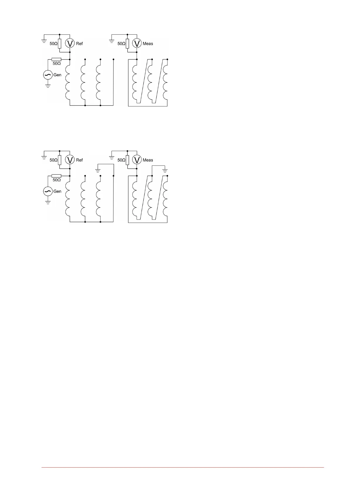
4. In the Inductive Inter-Winding, IIW (Transfer Admittance, TA) measurement, the signal is applied to a
terminal on the HV side, and the response is measured on the corresponding terminal on the LV side,
with the other end of both windings being grounded.
Example of labeling is “A-a1 [IIW, GND N,n1]” where GND N, n1 means ground terminal N (H0) and ground
terminal n1 (X0). The low frequency range of this test is determined by the winding turns ratio (slightly
aected by the 50 ohm load at the “Measure”-side.)
Appendix
www.megger.com FRAX-series 61
 Loading...