33
Analog output terminal wiring
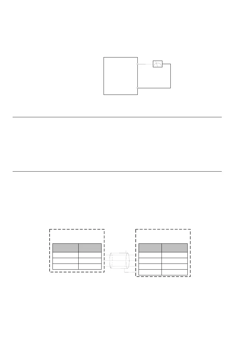
The external analog meter of the analog output terminals AO1 can indicate various parameters. The analog
output of the voltage/current is selected via the jumper, and the output range of the analog voltage/current is
selected in the function code P10.22. The terminal wiring mode is
as shown in Fig. 3-7.
Fig. 3-7 Analog output terminal wiring
Note
1. When using analog input, filter capacitor or common mode inductor can be installed between the input
signal and GND.
2. The voltage of the analog input signal shall not exceed 12V.
3. The analog input/output signal is vulnerable to external interference. Shielded cable shall be used and
reliably grounded, and the wiring length shall be as short as possible.
4. The analog output terminal can withstand the voltage no more than 12V.
Communication interface wiring
MV200 drive provides the RS485 serial communication interface for the users. A control system of single
host/single slave or single host/multiple slaves can be created through the following wiring methods. With the
host device (PC or PLC) software, real time monitoring, remote control, auto control and more complicated
running control (e.g., infinite multi-stage PLC running) can be realized on the drive within the network.
1. Connection of the drive and the host device with RS485 interface:
Fig. 3-8 RS485 communication wiring
Function Terminal
Signal-
RS485-
RS485+
MV200
Signal GND
GND
Function
Terminal
Signal -
RS485-
Signal +
RS485+
Host
Signal GND
GND
Shield cable
PE
Enclosure
Signal+
O1
GND
nalog mete
MV200
0: 0~10V(or 0~20mA)
1: 2~10V(or 4~20mA)
Unit place of P10.22: AO1 select
 Loading...