34
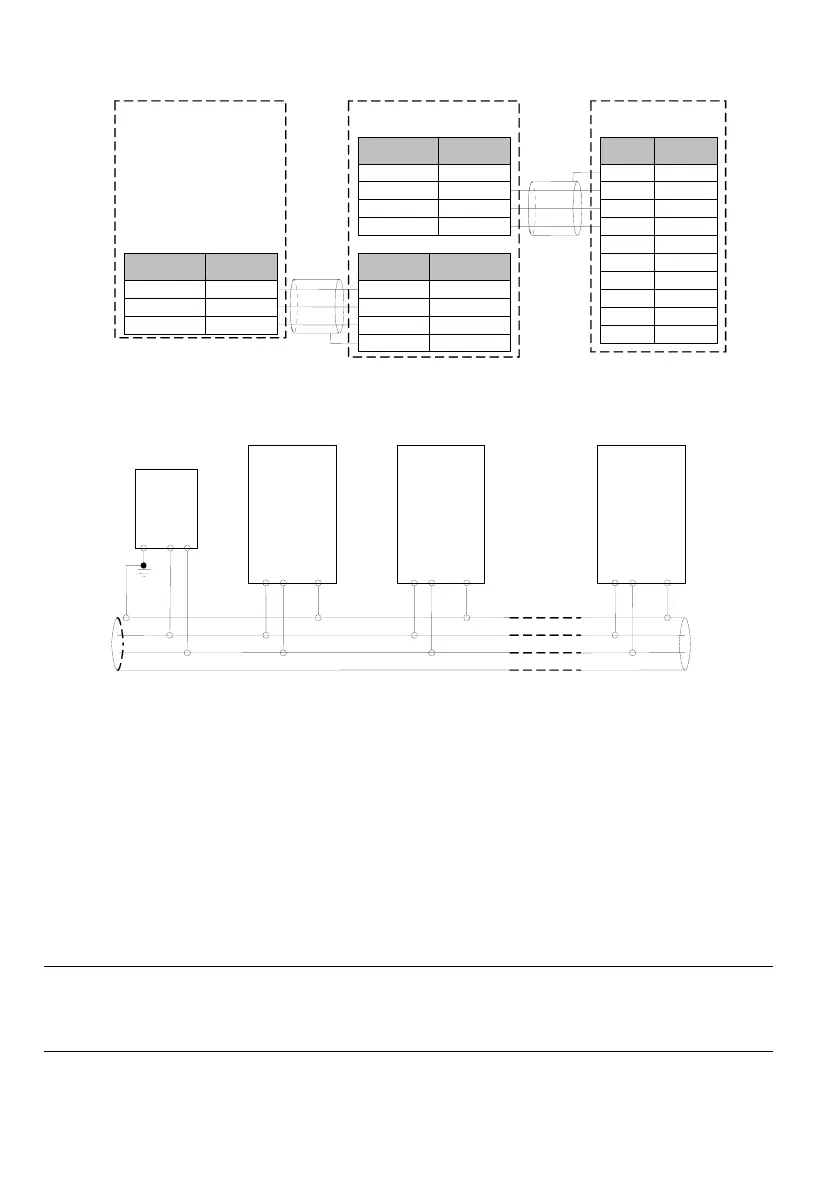
2. Connection of the drive and the host device with RS232 interface:
Fig. 3-9 RS485-(RS485/232)-RS232 communication wiring
3. Wiring for connecting several drives in the same RS485 system:
Fig. 3-10 Recommended wiring diagram for the communication between PLC and several drives
(the drives and motors are reliably grounded)
If normal communication still cannot be realized through the above wiring, take the following measures to
correct it:
1
) Provide separate power supply to the PLC (or host device) or isolate its power supply. In case the
external interference is severe, to protect the PLC (or host device) from interference, isolate the
communication wire.
2
) If the RS485/RS232 converter is used, provide separate power supply to the converter.
3
) Use magnetic ring on the communication wire.
4
) If the field conditions permit, reduce the drive carrier frequency.
Note
1. In the applications with large interference, the RS485 converter with isolation shall be used.
2. The RS485 cannot withstand the voltage higher than 30V.
PLC
MV200
+RS485- PE
MV200
+RS485- PE
MV200
+RS485- PE
SG +RS485-
RS485 cable
Signal -
RS485-
Signal +
RS485+
FunctionTerminal
Signal -
RS485-
Signal +
RS485+
Function
Terminal
+5V power
+5V
DATA TXD
TXD
DATA RXD
RXD
Power GND
GND
Pin No.Signal
Enclosure
PE
2RXD
3TXD
5GND
4DTR
6DSR
9RI
1CD
7RTS
8CTS
Shield cable
MV200
RS485/232 converter
Host
RS232(DB9)
Signal GND
GND
Signal GND
GND
PE Enclosure
Function Terminal
Shield cable
 Loading...