35
Wiring for Multi-functional input/output terminals
The multi-functional input/output terminals of MV200 include X1~X6. X1~X6 are opto-isolated circuits, as
shown in the following figure. PLC is the common terminal for X1~X6. The typical wiring methods are as
below:
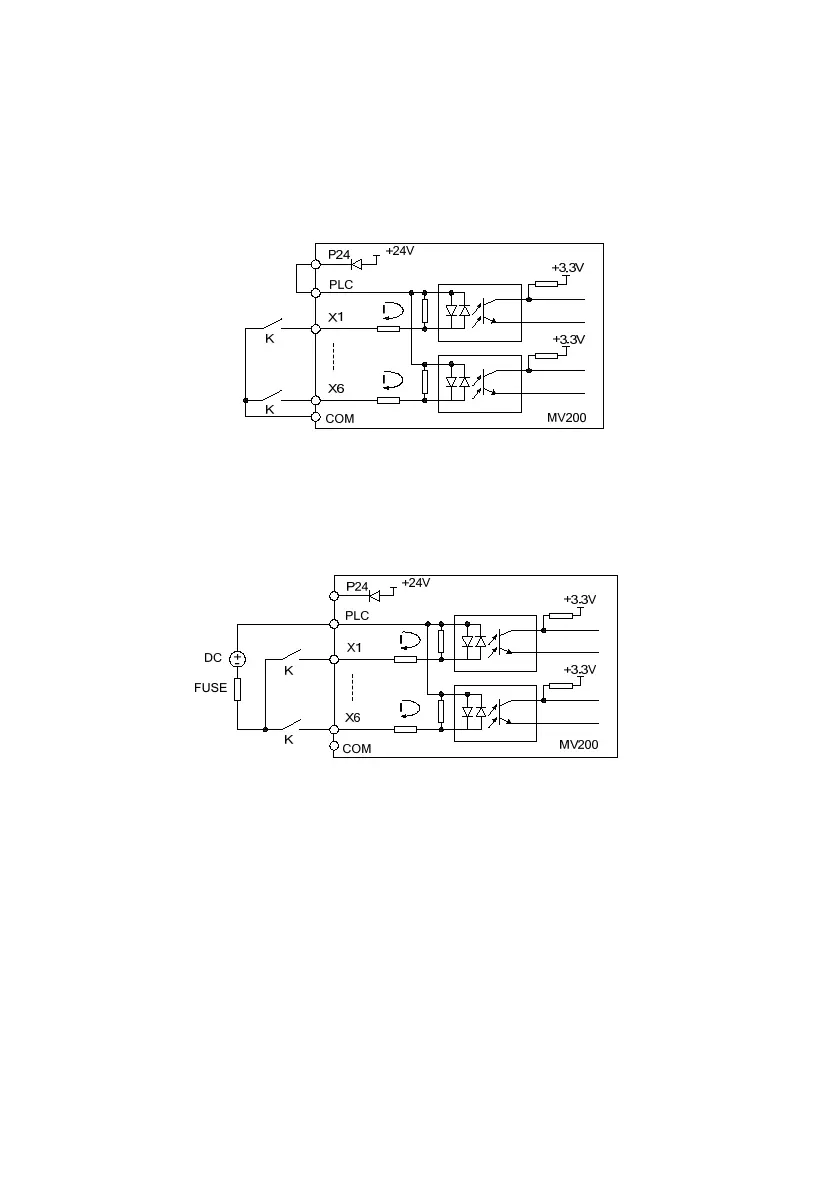
1.Dry contact mode (X1~X6)
1) When using the internal +24V power supply of the drive, the wiring mode is as shown in Fig.3-11.
Fig. 3-11 The wiring mode when using the internal +24V power supply of the drive
2) When using the external power supply (which shall meet the UL CLASS 2 standard, and 4A fuse shall be
installed between the power supply and the interface), the wiring mode is as shown in Fig.3-12 (be sure to
remove the short circuit plate between PLC and P24).
Fig. 3-12 The wiring mode when using the external power supply
2.Source (drain) mode
1) When the internal +24V power supply is used and the external controller is the NPN common emitter output,
the wiring mode is as shown in Fig. 3-13.
 Loading...