36
P24
+24V
PLC
X1
+3.3V
X6
+3.3V
COM
I
I
MV200
External
Controller
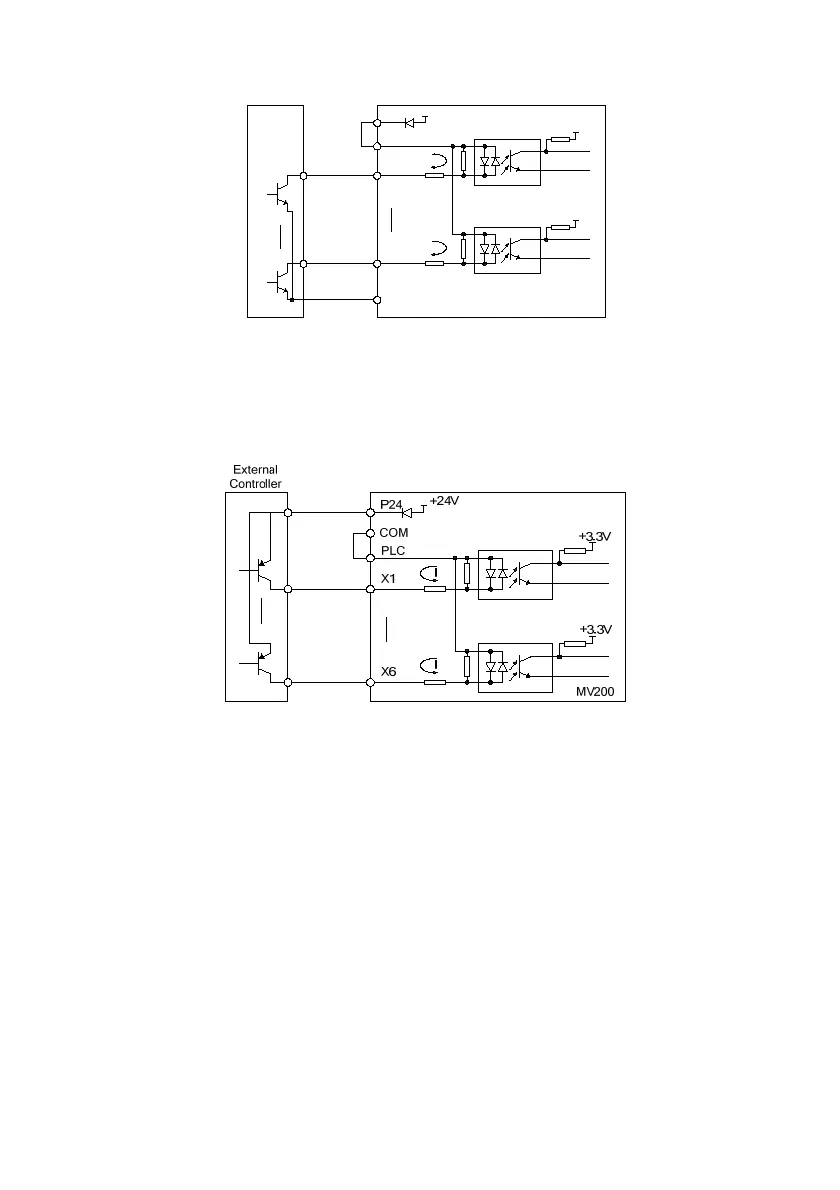
Fig. 3-13 The source connecting mode when using the internal +24V power supply of the drive
2) When the internal +24V power supply is used and the external controller is the PNP common emitter output
(
note: be sure to remove the short circuit plate between the user terminal PLC and P24 first, then connect it
between PLC and COM terminals firmly), the wiring mode is as shown in Fig. 3-14.
Fig. 3-14 The drain connecting mode when using the internal +24V power supply of the drive
3) The source connecting mode when using the external power supply (
note: be sure to remove the short
circuit plate between the user terminal PLC and P24) is as shown in Fig. 3-15.
 Loading...