37
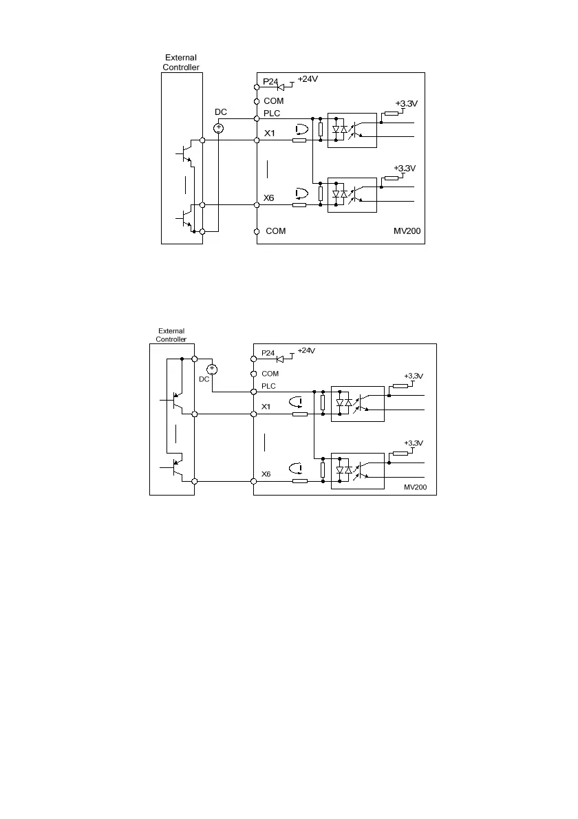
Fig. 3-15 The source connecting mode when using the external power supply
4) The drain connecting mode when using the external power supply (note: be sure to remove the short circuit
plate between the user terminal PLC and P24) is as shown in Fig. 3-16.
Fig. 3-16 The drain connecting mode when using the external power supply
Wiring for Multi-functional output terminals
1. When the Multi-functional output terminals Y1 and Y2 use the internal 24V power supply of the drive, the
wiring mode is as shown in Fig.3-17.
Warning: The inductive load (such as relay) shall be anti-parallel with the fly-wheel diode!
 Loading...