38
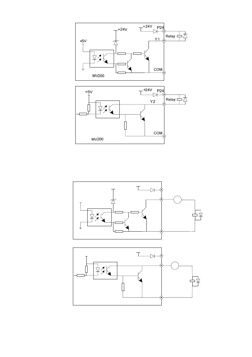
Fig. 3-17 Wiring mode 1 of Multi-functional output terminal
2. When the multi-functional output terminals Y1 and Y2 use the external power supply, the wiring mode is as
shown in Fig.3-18.
Warning: The inductive load (such as relay) shall be anti-parallel with the fly-wheel diode!
MV200
P24
COM
+24V
+5 V
Y1
+24V
Relay
+
-
DC
MV200
P24
COM
24V
+5V
Relay
Y2
+
-
DC
Fig. 3-18 Wiring mode 2 of multi-functional output terminal
3. When the digital pulse frequency output DO (Y1 terminal used as DO) uses the internal 24V power supply
of the drive, the wiring mode is as shown in Fig.3-19.
 Loading...