39
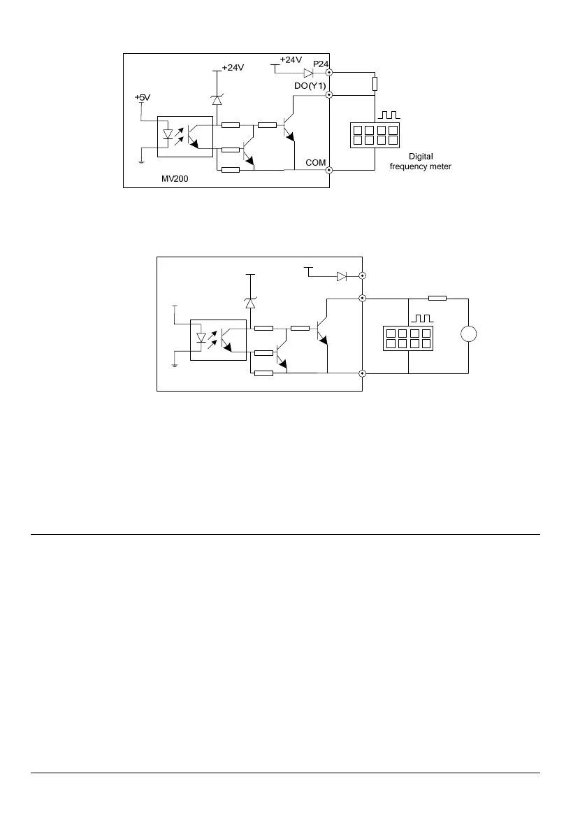
Fig. 3-19 Connecting mode 1 of output terminal DO
4. When the digital pulse frequency output DO (Y1 terminal used as DO) uses the external power supply, the
wiring mode is as shown in Fig.3-20.
MV200
P24
COM
+24V
+5V
DO (Y 1
)
+24V
4.7k
+
-
DC
Digital
frequency
meter
Fig. 3-20 Connecting mode 2 of output terminal DO
Wiring for relay output terminals TA, TB and TC
In the case of drive inductive load (e.g., electromagnetic relay, contactor), the surge absorption circuit shall be
installed, such as the RC absorption circuit (whose leakage current shall be less than the holding current of
the controlled contactor or relay), piezoresistor or fly-wheel diode (used in DC electromagnetic circuit, and
correct polarity shall be ensured during the installation). The components of the absorption circuit shall be
installed near the two ends of the windings of the relay or contactor.
Note
1. Do not short circuit the P24 terminal and COM terminal, otherwise, the control board may be damaged.
2. Please use the multi-core shielded cable or twist cable (cross section area: above 1mm
2
) to connect the
control terminals.
3. When using the shielded cable, the near end of the shielded layer (the end near the drive) shall be
connected to the grounding terminal PE of the drive.
4. The control cables shall be kept away from the main circuit and strong current lines (including power cable,
motor cable, relay cable, contactor connecting cable, etc.) for at least 20cm, and they shall not be laid in
parallel pattern. It is suggested to adopt vertical wiring to avoid the drive mis-operation caused by
interference.
5. For the non-24V relay, appropriate resistor shall be selected according to the relay parameters and
connected in series to the relay circuit.
6. The digital output terminal cannot withstand the voltage higher than 30V.
 Loading...