47
The higher harmonics of the leakage current that passes the distribution capacitors between the output cables
of the drive may cause the mis-operation of the external thermal relay. Especially the drives with small
capacity (7.5kW and below), when the wires are very long (over 50m), the leakage current will increased
relatively, which is easy to cause the mis-operation of the external thermal relay.
Suppression measures:
·Reduce the carrier frequency, but the motor noise will increase.
·Install reactor at the output end.
To reliably protect the motor, it is recommended to monitor the motor temperature with the temperature sensor,
and use the overload protection function (electronic thermal relay) of the drive instead of the external thermal
relay.
3.3.6 Proper EMC installation of drive
Partition principle
In the drive system formed by the drive and motor, the drive, control unit and sensor are installed in the same
cabinet. The noise is mainly suppressed at the main connection points, therefore, radio noise filter and
incoming reactor shall be installed in the cabinet. The cabinet shall also meet the EMC requirement.
To isolate the noise source and noise receiver through physical space in the mechanical/system stage is the
most effective but most expensive measure to reduce the interference. In the drive system formed by the drive
and motor, the noise source includes the drive, braking unit and contactor. The noise receiver includes the
automation device, encoder, and sensor.
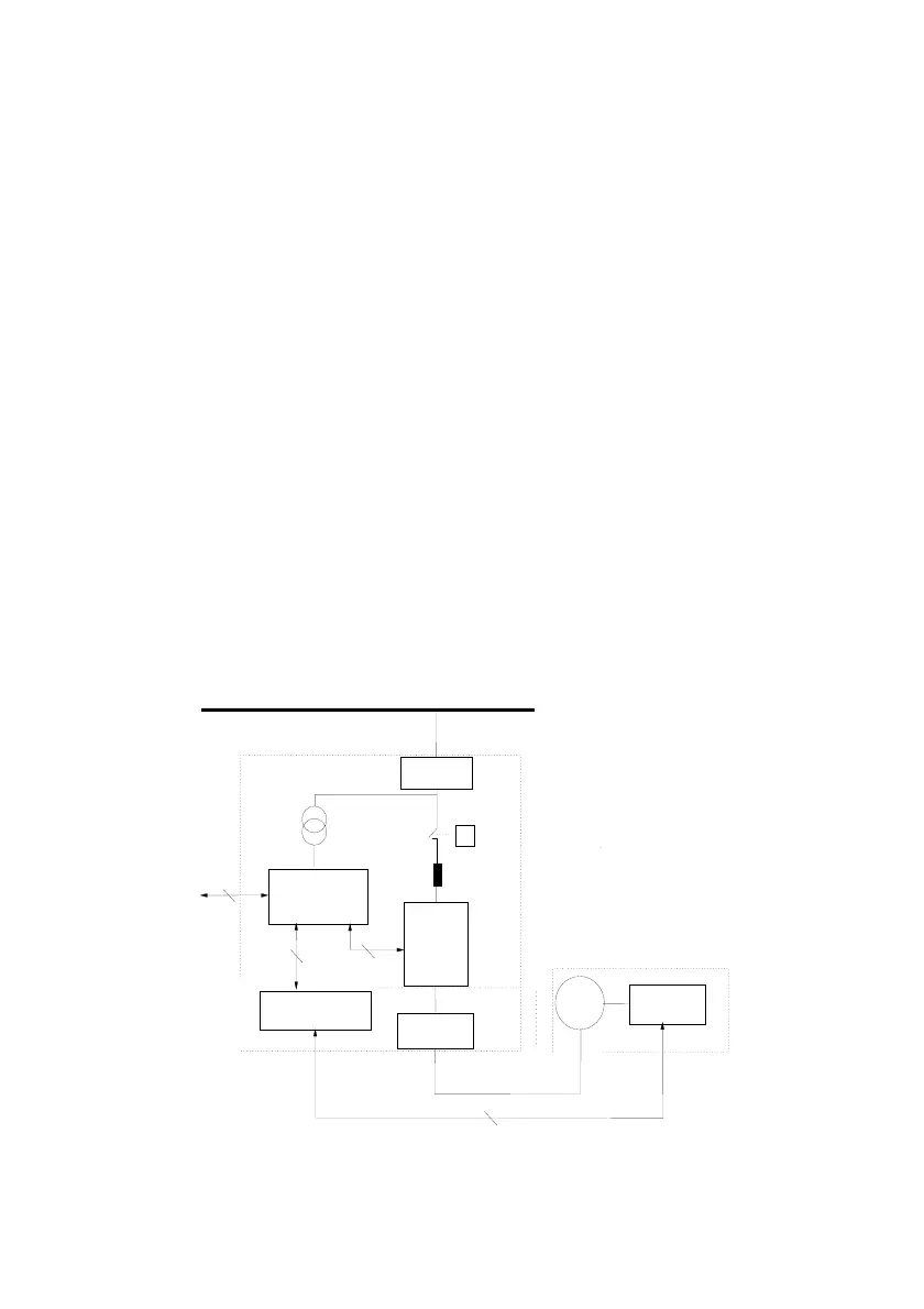
Different EMC zones are divided according to the electric characteristics in the mechanical/system design. It
is recommended to install the device in the zone as shown in Fig.3-33.
Fig. 3-33 Schematic diagram for the recommended partition for drive EMC installation
Input filter
Drive
Mechanical
system
Manufacturing
machine
rea VI
Motor
Input reactor
rea II
Line noise
filter
Grounded
separation board
rea IV
Power cable
Detecting signal cable
Motor cable
rea I
Electric cabinet
rea III
rea V
Sensors
Control device
 Loading...