48
Note:
Area I: the control power transformer, control system, sensor, etc.
Area II: the interface for the signal and control cables, which shall have certain immunity
Area III: incoming reactor, drive, braking unit, contactor, and other noise source
Area IV: output noise filter and its wiring
Area V: power supply (including the radio noise filter wiring)
Area VI: motor and its cable
·There shall be space isolation between the zones to realize electromagnetic decoupling.
·The minimum spacing between the zones shall be 20cm.
·The zones shall be decoupled via the grounding plate. Cables of different zones shall be laid in different
cabling troughs.
·The filters shall be installed at the interfaces between the zones.
·All the communication cables (e.g., RS485) and signal cables leading out from the cabinet must be shielded.
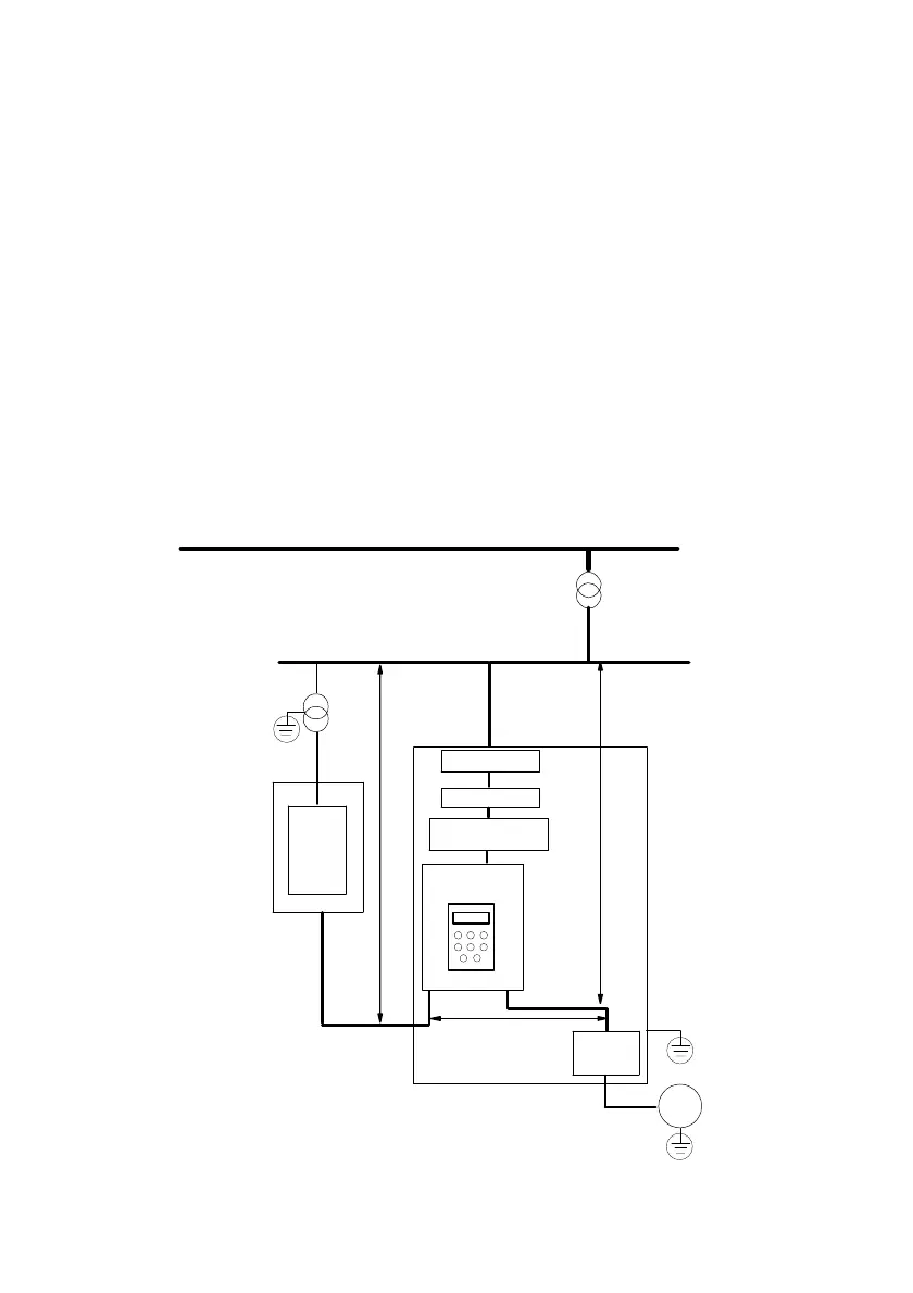
Electric installation diagram for the drive
10kV
Power
transformer
Isolation
transformer
Power cable of
meter
Metal
cabinet
> 20cm
PLC or
meter
Control
signal cable
Power cable of
drive
Filter
AC input reactor
> 30cm
Drive
> 50cm
AC output
reactor
Motor cable
Metal
cabinet
Motor
Circuit breaker
Fig. 3-34 Installation diagram for the drive
 Loading...