Page 58 www.menzimuck.com
Control and Display elements
1
5
7
2
3 4
6
8
Note !
Symbols
The operation and status display symbols only appear when they
are active.
Note !
Central lubrication
Note for machines with central lubrication: after lling the grease
container, this must be conrmed using the central lubrication
control. To do so, please read the operating manual for the cen-
tral lubrication control.
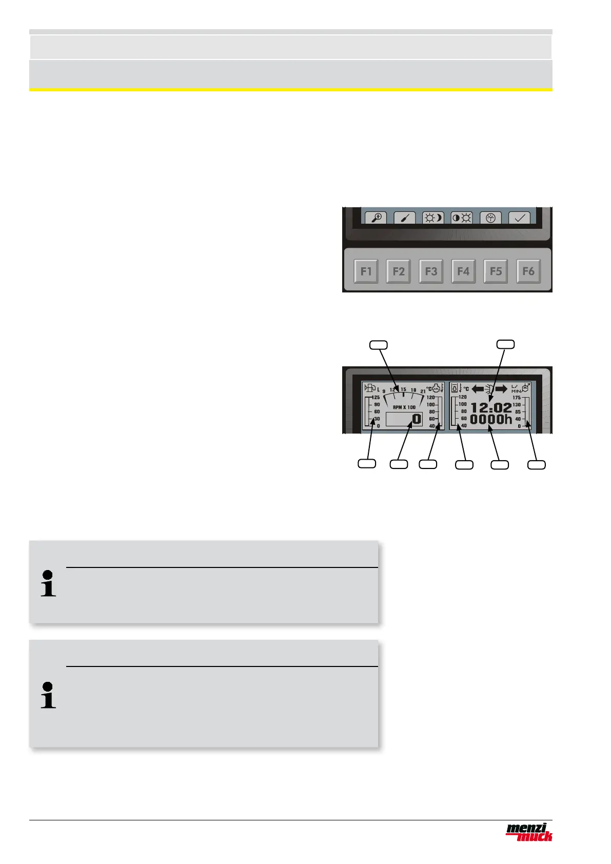
User controls
A set of keys is located beneath the display (F1 - F6). Above the-
se keys, symbols indicate which menu or command is activated
by pressing the key.
Example main menu:
F1 Detail menu
F2 Powerline setting (not activ)
F3 Day/night switch. The screen colours are inverted and the
keys are lit up.
F4 Brightness / contrast setting
F5 Date / time setting
F6 Conrmations of the message windows and other messages
Main displays
Using bar graphs and a graphical speed display, the driver is
continuously informed of the most important operating status de-
tails, all at once.
1 Tank display
2 Cooling water temperature
3 Hydraulic oil temperature
4 Powerline setting
5 Numerical display of rpm
6 Graphical display of rpm
7 Operating hours
8 Clock
Operation and status display
 Loading...