Exhaust System
Page 6A-12 90-863758060 AUGUST 2006
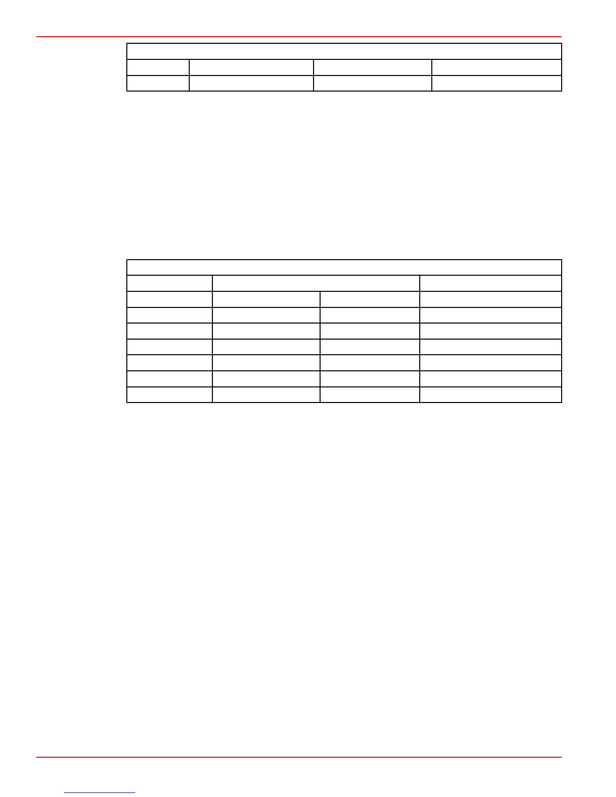
Minimum Exhaust Hose Size
496 MAG 10.2 cm (4 in.) 10.2 cm (4 in.) 12.7 cm (5 in.)
All others 10.2 cm (4 in.) 10.2 cm (4 in.) 10.2 cm (4 in.)
• Sharp bends in exhaust hoses should be avoided.
• Exhaust hoses can be installed at up to a 5° angle relative to the exhaust elbow outlets.
Refer to Exhaust Hose Connections.
• Exhaust elbows must be the prescribed distance above the water line. Install risers if
needed. See Measuring Exhaust Elbow Height.
• The exhaust hose attached to the exhaust elbow must have a minimum of 10°
downward slope. On longer hose applications, slope can be reduced to 3° in the portion
of the exhaust system that is more than 46 cm (18 in.) away from elbow.
NOTE: Mercury MerCruiser's recommendations more stringent than ABYC
recommendation of a minimum drop in the exhaust system of ½ in. per foot with an overall
drop of not less than 10.2 cm (4 in.) between the exhaust elbow outlets and the boat outlets.
Slope Conversion
Degrees Drop vs. run Distance from elbow
3° 5/8 in./ft. 52 mm/m > 18 in.
6° 1¼ in./ft. 105 mm/m < 18 in.
7° 1‑7/16 in./ft. 122 mm/m < 18 in.
10° 2‑1/8 in./ft. 176 mm/m < 18 in.
12° 2½ in./ft. 212.5 mm/m < 18 in.
14° 2‑15/16 in./ft. 249 mm/m < 18 in.
19° 4‑1/8 in./ft. 344 mm/m < 18 in.
• The drop in the exhaust hose must be continuously sloping downward so that a low
spot does not exist at any point.
• Exhaust resonators can be used on any models, except 3.0L models, that may
experience a water intrusion problem. Refer to Exhaust Resonators.
• Through the hull exhaust fittings (flanges, outlets) must be equipped with internal
shutters and external flappers to prevent the reverse flow of water into the engine. Refer
to Exhaust Through The Hull Fittings.
• Exhaust outlets must be above the water line with the boat at rest in the water and a
full load aboard, as well as while underway. This is necessary to minimize engine back
pressure.
• Every exhaust hose connection should be secured with at least two hose clamps. The
clamps should be stainless steel and at least 13 mm (½ in.) wide. Clamps which rely
solely on spring tension should not be used. (ABYC Standard)
• The exhaust system must be adequately supported for proper orientation and to
prevent overstressing the exhaust manifolds and elbows. The support requirements
will vary with exhaust system design and the amount of G‑forces to be encountered.
• The through transom exhaust system must meet the exhaust back pressure
specification.
• The system must have the capability to be serviced, reassembled, and replaced while
maintaining all of the specifications. The boat builder must provide documentation,
such as manuals, drawings, or orientation marks on production assemblies.
• Check for absence of water intrusion and proper exhaust back pressure when finished.
See Checking for Water Intrusion and Exhaust Back Pressure.

 Loading...


