34
|
VIKING / VIKING COMBI
Rev. 2.0 (1.8.2017)
Installation
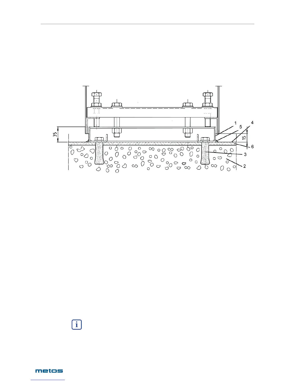
6.2.2. Installation on surface installation frames
The optional installation frame is to be installed according to the installation drawing. If t e fl oor is not
even, it might be necessary to straighten the installation frame to a position nearer to the horizontal by
putting some stainless steel spacers between the frame and the fl oor, so that the adjustment range of
the pillar is suffi cient.
The junction between the installation frame and the fl oor is sealed with silicone or similar.
1. Surface frame
2. Concrete casting
3. Fixing bolt for surface frame
4. Finished fl oor surface
5. Silicone mastic
6. Acrylic fi ller
Fixing bolts of the surface installation must be chosen according to the fl oor material. Recommended
type is a UKA 12x200 chemical bolt, which is suitable for different fl oor materials. Alternatively expansi-
on-shell bolts or equivalent can be used.
Place the kettle on the surface installation frame and adjust to a horizontal position with 4 adjusting bolts
which are in the corners of the pillars. When the kettle is in a horizontal position it must be fi xed to the
surface frame with the help of M12 fi xing bolts. The control pillar has 4 bolts and the support pillar has
2 bolts. Tighten the fi xing nuts carefully. Do not seal the space between the kettle pillars and surface
installation frames, as there must be enough change of air.
6.3. Electrical and water connections
The electrical and water connections for each kettle (single or group) are made to the right-hand kettle
pillar according to the installation drawing.
6.3.1. Electrical connection
Connections are to be done according to the installation drawing and the electric diagram.
The kettle is equipped with a decoupling switch, which separates the kettle totally from the electrical
network.