36
|
VIKING / VIKING COMBI
Rev. 2.0 (1.8.2017)
Installation
6.3.4. Steam and condensate connections (steam heated models)
The steam and condensate connections of the Viking combi-kettle must be carried out by a person with
professional competence in the fi eld. Improper connections and piping may severely impact the correct
function of the kettle.
The location of the steam and condensate connection points appears from the installation drawing.
The maximum steam pressure in the kettle is 1 bar. The steam supply line must be fi tted with a one-way
valve, a shut-off valve, a fi lter, a pressure reduction valve and a safety valve set at 1,5 bar.
The condensate pipe must be on the same fl oor as the kettle or go to the fl oor below. Leading the con-
densate pipe to the fl oor above the kettle is not allowed, as it creates a water trap that prevents normal
function of the kettle.
The condensate pipe must be free from pressure created by other appliances.
6.4. Ventilation
The heat and steam load of the kettle must be taken into account in the kitchen’s ventilation plan. A ven-
tilation hood must be installed above the kettle, because plenty of steam is released when the kettle lid
is opened. When dimensioning the ventilation hood, the space requirement for opening the lid must be
taken into account (see installation drawing).
6.5. Other installations
In case the combi-kettle being installed is provided with a self-control option (HACCP), and it is taken
into use, the data cabling and the installation of the program must be carried out according to separate
instructions.
6.6. Adjusting the tilting
Ensure that the kettle pillars are in a horizontal position. If not, adjust according to the installation instruc-
tions. Ensure that the rim of the kettle also is horizontal. If not, adjust the tilting as follows.
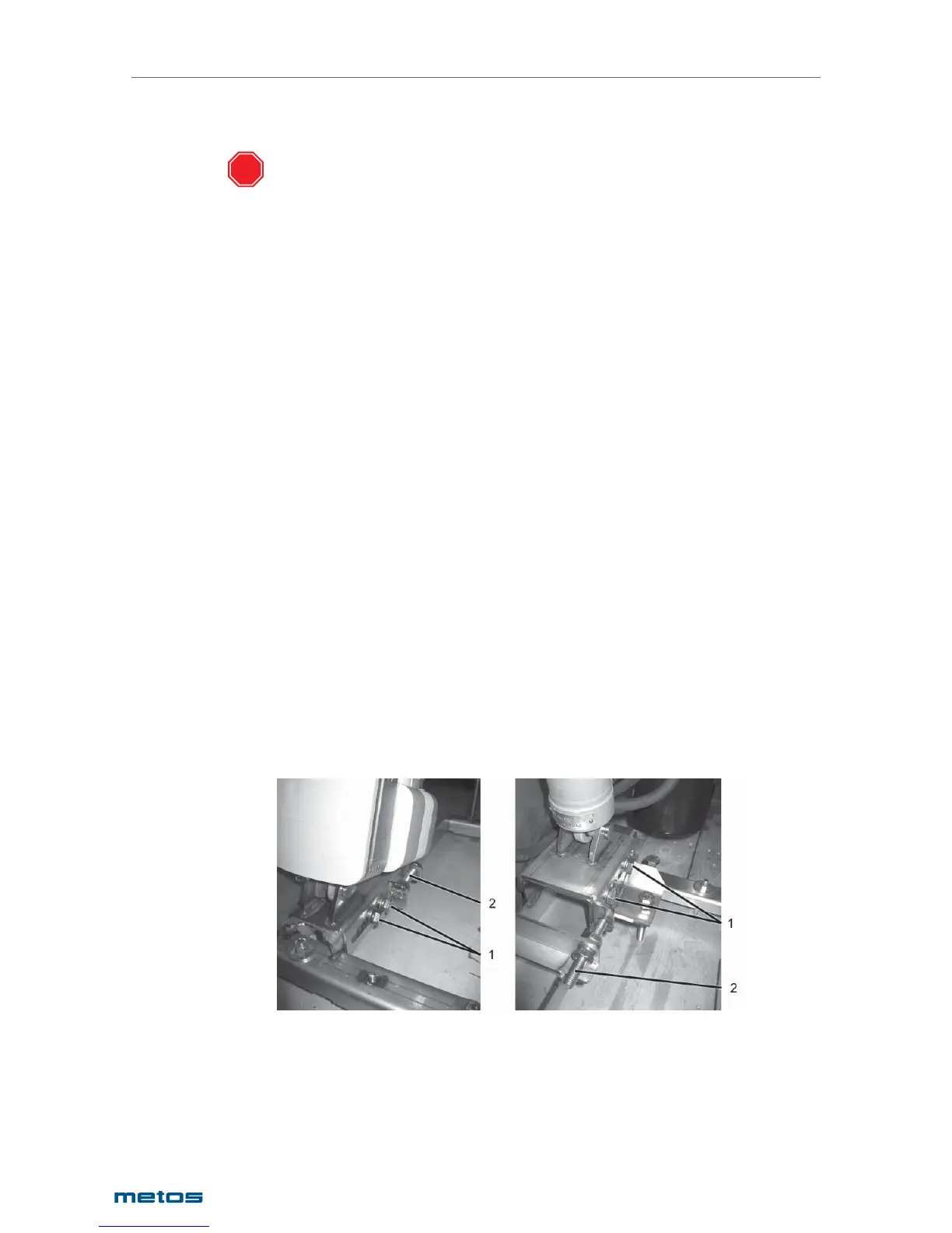
The adjustment is done from the lower mounting point of the tilting motor as follows:
1. Open the locking screw
2. Open the locking nut.
Viking 40-300 l, Viking Combi 40-200 l Viking Combi 300-400 l
STOP
1. Locking screw
2. Adjusting screw
3. Adjust with the adjusting screw which is inside the U-profi le.
4. Lock with the screw and tighten with the nut.
5. Finally check that the roller plunger of the tilting limit switch trips when the kettle is in an upright
position.