54
|
PROVENO E
Rev. 1.2 (24.08.2016)
Installation
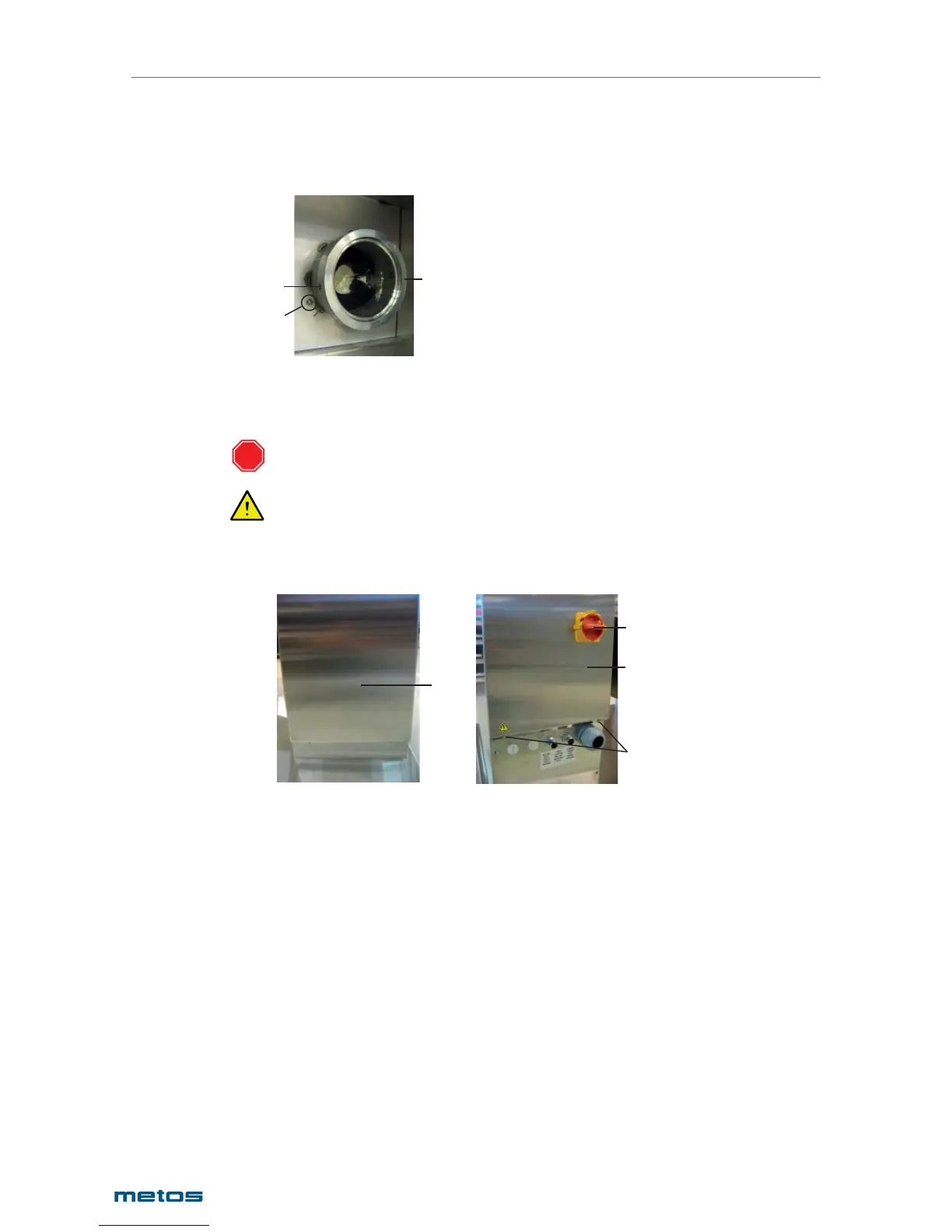
When the axle is pushed fully into the bearing and the stop ring makes contact with the bearing mount
the locking ring (1) and secure it with the three locking screws (2). After that the three screws (3) for
fastening the bearing cover plate can be refi tted.
1
3
2
1. Locking ring
2. Locking screw
3. Bearing cover fastening screw
After this the control pillar can be adjusted and installed as previously described
5.3. Electrical connections
The electrical connections of the Proveno combi-kettle can only be carried out by a qualifi ed electrician
having the necessary competence for the installation and service of electrical appliances.
The control pillar cover plate is a fi xed component, not intended for detaching. Do not force it upwards
when removing the front and rear cover plates.
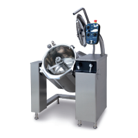
To make the electrical connections, the upper left-hand side plate, where the mains switch is located,
must be removed.
1
2
3
4
1. Front plate
2. Mains switch
3. Rear plate
4. Screw
Turn the mains switch (2) to the OFF position.
If the control pillar front plate (1) is in place, it must be fi rst detached by opening two screws (4) at the
lower section of the plate.
Detach the rear cover plate (3) by opening the screws (4).
STOP