MI 3309 BT DeltaPAT Single test
51
PRCD: Connect tested PRCD / device to an external
voltage socket. Connect the IEC cord to the
instrument´s MAINS terminal and PRCD (see Figure
5.36b). Or connect tested PRCD between test
socket and IEC connector of the DeltaPAT Connect
the instrument to mains voltage (see Figure 5.36c).
Depending on the type of PRCD, it may be
necessary to manually switch it on.
RCD: Connect the DeltaPAT MAINS terminal to
mains socket protected by tested RCD (see Figure
5.36a).
Press the TEST key
Test with IN, 0 (step 1).
(P)RCD should trip-out
Re-activate (P)RCD.
Test with IN, 180 (step 2).
(P)RCD should trip-out
Re-activate (P)RCD.
Test with 5IN, 0 (step 3).
(P)RCD should trip-out
Re-activate (P)RCD.
Test with 5IN, 180 (step 4).
(P)RCD should trip-out
Re-activate (P)RCD.
Test with ½IN, 0 (step 5).
(P)RCD should not trip-out
Test with ½IN, 180 (step 6).
(P)RCD should not trip-out
End of test.
Displayed results:
Main results ........... trip-out times at different currents / starting polarities
U ............................ voltage U
L-PE
Notes:
Consider any displayed warning before starting measurement!
Mains voltage is applied to the (P)RCD under test. Do not touch the equipment
under test or the test cord during the test.
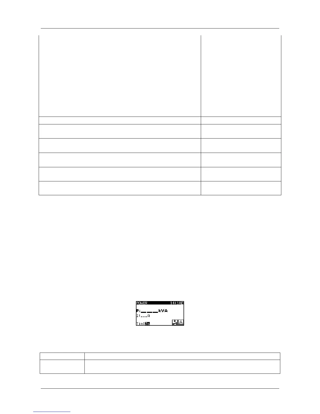
5.2.11. Power test
The DUT’s power consumption is measured in this test. The apparent power is a useful
indication of proper operation of the appliance.
Figure 5.38: Power test menu
Test parameters for the Power test
OUTPUT Test voltage [MAINS voltage]
TIME Measuring time [2 s, 3 s, 5 s, 10 s, 30 s, 60 s, 120 s, 180 s, --- s
(continuous measurement)]
Test circuit for the power test

 Loading...