120
To switch between the modes, keep pressing “F” direct mode button. The display includes the symbols for
currently selected mode (PWM or HF).
18.14.1. Control in the frequency mode
• Press F direct mode button. The calibrator switches to PWM mode. If HF mode is desired, press F button
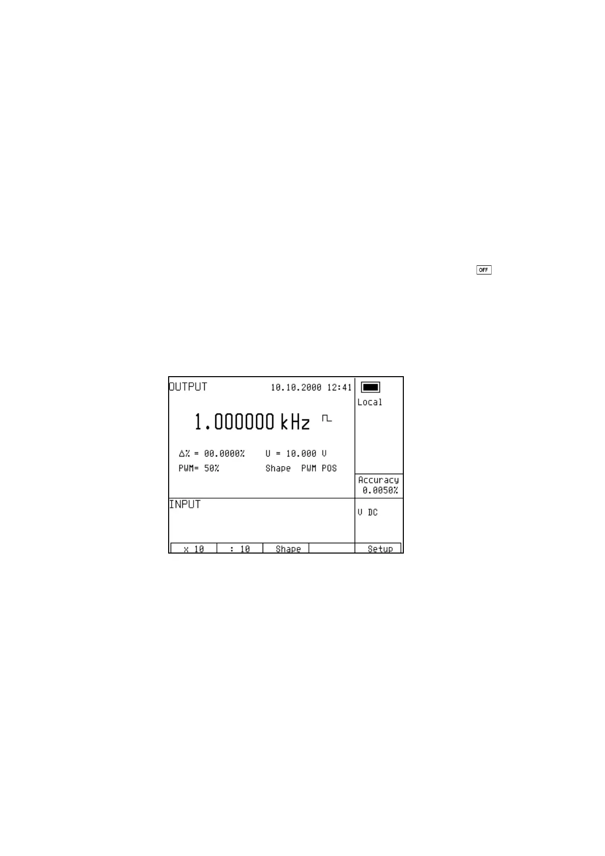
once more. The main data on the display is the frequency.
• The display shows the following data:
* set frequency
* relative deviation of frequency
* signal amplitude (PWM mode ) or attenuation (HF mode)
* duty cycle (PWM mode only)
* signal shape: PWM NEG / POS / SYM (PWM mode only)
• Set the frequency using numeric keyboard, cursor buttons or potentiometer. Output signal is not yet
connected to the output terminals. The information section of the display shows the symbol
which informs about the disconnection of output terminals...
•
Connect the object to be calibrated to FREQ terminal.
• Press OUTPUT button.
• Red LED is lit above the OUTPUT terminals to indicate the connection of signal to the output connector.
• Output signal with set frequency is present at the output connector.
Note
• “FREQ” connector must not be overloaded. In 100 mV to 10V voltage range, maximum load is 5 mA.
In other voltage ranges, maximum load is 0.1mA. If the output is overloaded, the set value is not
guaranteed.
• The output is short-circuit proof.
• The outer casing of the connector is electrically connected to the chassis of the calibrator.
 Loading...


