■■■■■■■■■■■■■■■■■■■■■■
Index
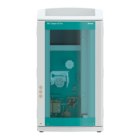
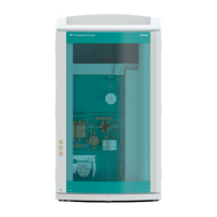
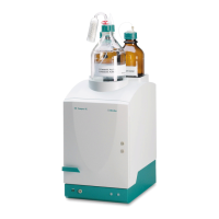
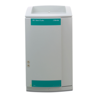
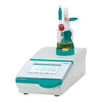
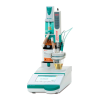
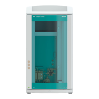
930 Compact IC Flex Oven SeS/PP/Deg (2.930.2560)
■■■■■■■■
41
Index
A
Adsorption cartridges
Connection ........................ 26
Aspiration tubing for eluent ...... 17
B
Baseline
Condition ........................... 38
C
Capillaries
Installation ......................... 11
Cartridges
Connection ........................ 26
Column
see "Separation column" .... 35
Computer connection ............... 30
Conditioning ............................ 38
Connect
To computer ....................... 30
To power grid ..................... 31
Connections
Installation ......................... 11
D
Degasser
Sample degasser ................. 29
Drainage tubing
Installation ......................... 14
E
Electrostatic charge .................... 6
Eluent
Aspirate .............................. 17
Eluent bottle
Installation ......................... 16
Equilibration ....................... 33, 38
F
Filter
see "Inline filter" ................. 19
G
Guard column
Installation ......................... 34
Rinse .................................. 35
H
High-pressure pump
Protection .......................... 13
I
IC column
see "Separation column" .... 35
Injection valve ............................ 3
Installation ......................... 19
Inline filter ................................ 19
Installation
Connections ....................... 11
Drainage tubing ................. 14
Eluent bottle ....................... 16
Guard column .................... 34
Injection valve .................... 19
Leak sensor ........................ 15
MCS ................................... 26
Peristaltic pump .................. 24
Pulsation absorber .............. 19
Pump tubing ...................... 24
Sample degasser ................. 29
Separation column ............. 35
Suppressor ......................... 19
L
Leak sensor
Installation ......................... 15
Leak-tightness .......................... 34
M
MCS
Capillary connection ........... 26
Cartridge connection .......... 26
Installation ......................... 26
P
Peristaltic pump
Installation ......................... 24
Power connection .............. 31, 32
Pulsation absorber
Installation ......................... 19
Pump tubing
Install ................................. 24
R
Rinse
Guard column .................... 35
Separation column ............. 36
S
Safety instructions ...................... 5
Sample degasser
Installation ......................... 29
Separation column
Installation ......................... 35
Protection ...................... 3, 19
Rinse .................................. 36
Service ....................................... 5
Supply voltage ............................ 5
Suppressor
Install rotor ......................... 19
Installation ......................... 19
Suppressor drive
see "Suppressor" ................ 19
T
Transport locking screws ........... 12
Tubings
Installation ......................... 11
V
Vacuum pump
Protection .......................... 13
Valve
See also "Injection valve" .... 19