10 3 R 74 en
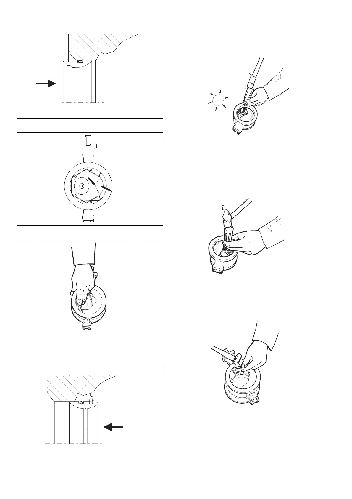
Check that the spring angles extend to the control
face.
Place a screwdriver on each visible spring angle one
after the other and knock the spring into the groove,
see Fig. 29.
Turn the segment 180° clockwise and knock the rest
of the spring angles into the groove, Fig. 30. A spe-
cial tool available from the manufacturer may also
be used for the work phases in Figs. 29 and 30.
Use a plastic spindle to ensure that the seat is cor-
rectly placed and can move freely, Fig. 31.
4.6 Dismantling the valve
Turn the valve into the closed position.
Remove the pin lockings either by grinding or using
a spindle. Detach the pins (14 and 15) by drilling, Fig.
32. Be careful not to damage the original bores.
Note! The pins and the drive shaft have been
Fig. 25 Precompression of the lip seal
Fig. 26 Mounting the seat
Fig. 27 Slipping the seat into the body
Fig. 28 Pushing the the spring angles against the control
face
Fig. 29 Knocking the spring into the groove
Fig. 30 Knocking the spring after turning the seat around
Fig. 31 Securing with a plastic spindle

 Loading...