3 R 74 en 11
secured by welding in the titanium version and in
the acid-resistant high-consistency version S.
Detach the retainer plates (30).
Detach the gland packings (20).
Remove the shafts (11 and 12), Fig. 33.
Lift the segment from the body.
Remove the bearings (16 and 17) and clean the bear-
ing spaces.
Remove the seat by pushing it evenly inside the
body.
4.7 Inspection of removed parts
Clean the removed parts.
See if the shafts (11, 12) and bearings (16, 17) are
damaged.
Check if the sealing surfaces of the segment and the
seat (4) are damaged.
If necessary, replace the parts with new.
4.8 Assembly
The bearing material of the standard construction
valves is PTFE-impregnated stainless steel net. The
bearings for the high temperature valves are cobalt
alloy bushings which are mounted into the body
together with the shafts. High temperature is over
+260 °C.
Put the bearings (16, 17) in their places.
Mount the S, U or T-seat as explained in 4.5.2.
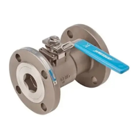
For A-seat (Fig. 34), mount the retaining ring (7) to
the groove in Body (1). Install back seal (6), support
ring (8) and spring (5) to the seat (7). Mount the
assembled seat package to the body. Use a plastic
spindle to ensure that the seat is correctly placed.
Mount the segment in the body in the closed posi-
tion. In the low Cv version, insert the filling ring (22)
between the drive shaft (11) and segment (3). Press
the segment to fit the shaft (12).
For A-seat special compression tool is needed for
compress the spring to mount the shaft and drive
shaft. See Fig. 33.
Install the drive shaft (11). Note the location of the
pin hole and the keyway. See Figs. 36 and 37.
High temperature-construction: Mount the bear-
ings (16, 17 and 18) into the shafts. Spray a thin layer
of dry lubricating fluid, e.g. Molykote 321R or equiva-
lent, into the inside surface of the bushing and the
shaft bearing groove. Press the bushing with a tight-
ening ring into the shaft bearing groove and fit the
shaft with the bearings carefully into the body
through the tightening ring.
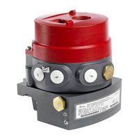
Please note the depth of the hole (L) for the conical
pin, Fig. 32. Use a former to check the proper shaft
position of low Cv valves, see Fig. 36 . Put the pins
(14, 15) in their places and lock them, Fig. 37. Both
pins are locked with TIG welding in the high-consist-
ency acid-resistant version and in the standard and
high-consistency titanium versions. Moreover, the
drive shaft is welded to the segment in the high-con-
sistency versions. Contact the manufacturer for more
information.
Fig. 32 Drilling the pin
Fig. 33 Installing the shafts
Conical pin
part no. 15
DN 25...500
A - A
A
Cylindrical pin
part no. 14
DN 25...40
Cylindrical pin
part no. 14
DN 50...500
DN DRILL ø (mm) L (mm)
25, 40 2,0 18
50, 65 3,5 25
80, 100 4,2 33
150 5,0 43
200 7,0 52
250, 300 8,8 60
350, 400 12,0 90
500 16,0 120
L
Fig. 34 A-seat
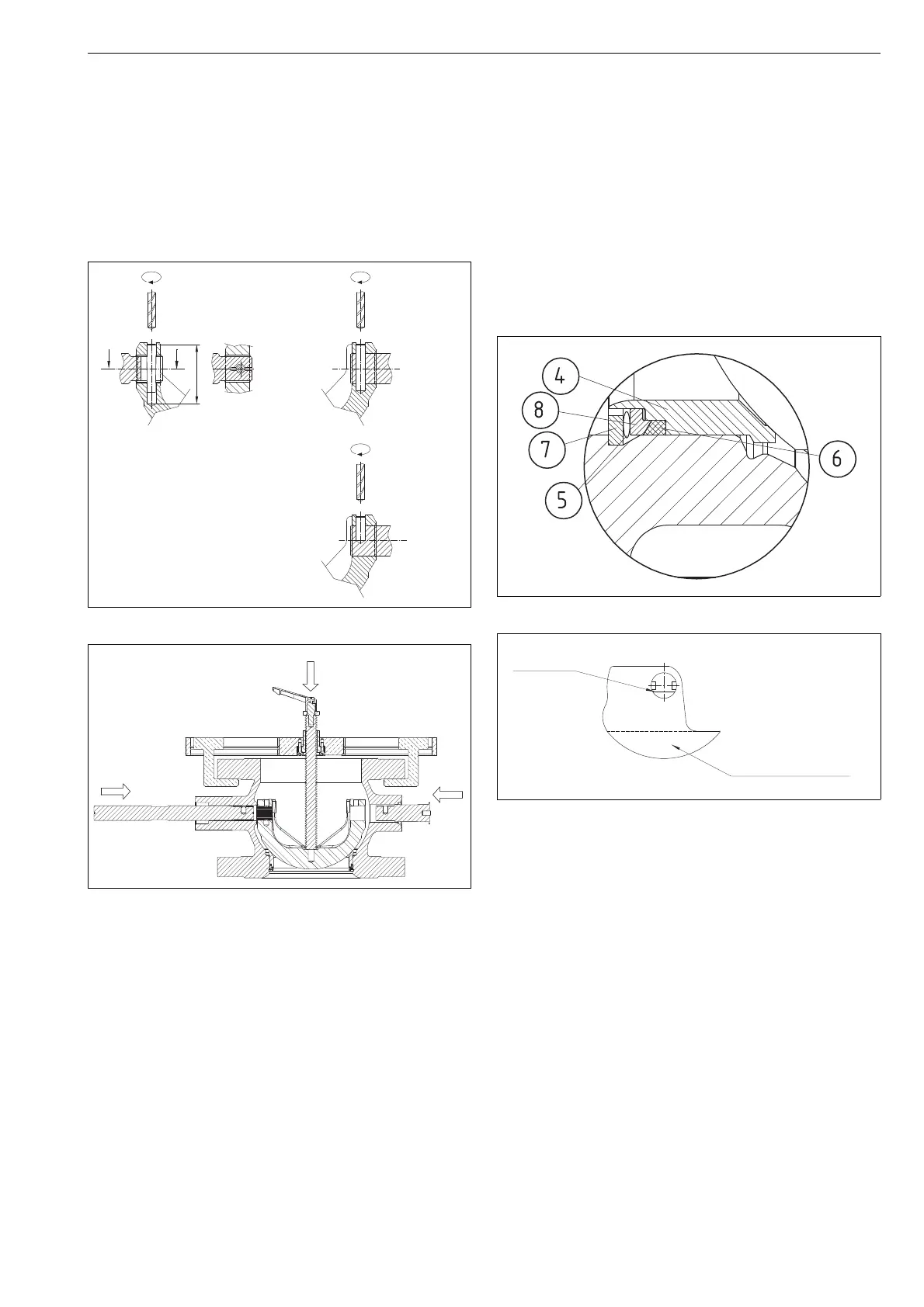
Fig. 35 Segment and shaft positions
Spherical surface
marker line

 Loading...