3 R 74 en 3
1 GENERAL
1.1 Scope of the manual
This manual provides essential information on R series V-
port segment valves, i.e. RA, RE and RE1-series valves. Actu-
ators and other accessories are only discussed briefly. Refer
to the individual manuals for further information on their
installation, operation and maintenance.
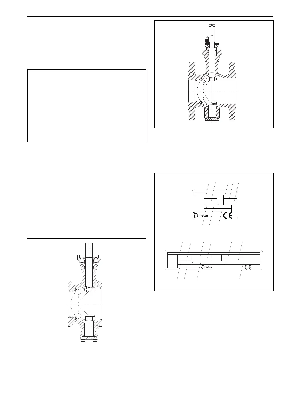
1.2 Valve construction
RA, RE and RE1-series valves are V-port segment valves
installed between flanges. RE series valves are flanged V-
port segment valves. The body is in one part; the shaft and
the segment are separate. Shaft blow-out is prevented by
plates mounted against the shaft shoulder. See Figs. 1 and 2.
The valve is either soft or metal seated. Tightness derives
from the spring force pressing the seat against the segment.
The structure of the valve supplied may vary, depending on
the customer’s requirements. The detailed structure is
revealed by the type code shown on the valve identification
plate. The type code is explained in Section 15.
The valve is designed for both control and shut-off applica-
tions.
1.3 Valve markings
Body markings are cast on the body. The valve also has an
identification plate attached to it, see Fig. 3.
Identification plate markings:
1. Body material
2. Shaft material
3. Segment material
4. Seat material
5. Maximum operating temperature
6. Minimum operating temperature
7. Maximum shut-off pressure differential
8. Type designation
9. Valve manufacturing parts list no.
10. Pressure class
NOTE:
Selection and use of the valve in a specific application
requires close consideration of detailed aspects. Due to
the nature of the product, this manual cannot cover all the
individual situations that may occur when the valve is
used.
If you are uncertain about use of the valve or its suitability
for your intended purpose, please contact Metso Flow
Control business for more information.
For valves in oxygen service, please see also the separate
installation, maintenance and operating instructions for
oxygen service (see Metso document id: 10O270EN.pdf).
Fig. 1 Construction of a V-port segment valve, RA
Fig. 2 Construction of a V-port segment valve, RE/RE1
Fig. 3 Identification plate
ATTENTION:
TYPE
BODY
No.
SEAT
TRIM
max
ps
min
INSTALLATION OR SERVICING.
t
t
READ INSTRUCTIONS BEFORE
Made by
Metso Flow Control
XXXX
BODY
TRIM
SHAFT
SEAT
TYPE
RATING
No.
t max.
t min.
ps
ATTENTION: READ INSTRUCTIONS BEFORE INSTALLATION OR SER VICING. CONTACT METSO AUTOMATION FOR COPY.
Made by Metso Flow Control
XXXX
Sizes 25–80
Sizes ≥ 100
(1)
(3)
(5)
(6)
(7)
(4)
(9)
(8)
(1)
(3)
(5)
(6)
(8)
(9)
(2)
(4)
(7)
(10)

 Loading...