3 R 74 en 13
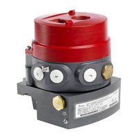
Prior to installation, the correct keyway position of the
valve has to be checked. The bushing has four keyways,
two of which are intended for valves with DIN key and
two for valve shafts with ANSI key. The ANSI keyway is
located in the middle of the half bushing, and the DIN
keyway is located in the split between the bushing
halves. Fig. 40 shows the keyway position when the
actuator is in a closed position.
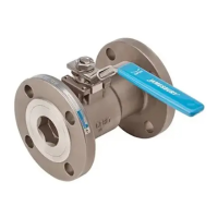
The open or closed positions of the actuator can be
identified either by using compressed air, see Fig. 41,
or by checking the position of the pointer at the end
of the drive shaft. The actuator is closed if the pointer
on the coupling plate is transverse to the direction of
the actuator’s main shaft.
Mount the actuator either directly on the valve, or
attach it to the valve bracket with four screws. The
tightening screw of the bushing should be loosened
before mounting, to allow the shaft to fit easily into
the actuator.
The actuator construction allows axial movement of
the drive shaft. Check, before the screw is tightened,
that the drive shaft is in the upper position of its axial
movement, which is its normal position (the mount-
ing position shown in Fig. 39). Checking is important,
as the actuator shaft drops down slightly when the
screw is tightened. The drive shaft axial movement
can be observed and measured before attachment to
a valve. The actuator drive shaft is in the upper posi-
tion when its upper surface conforms to Table 4, see
also Fig. 39.
The drive shaft will automatically find its correct
position if the installation tool H061904 (see Fig. 39)
is used. The installation tool is attached instead of
the coupling plate using M4 screws with the drive
shaft in lower position (before the valve is installed).
Tighten the nut of the tool in such a way that the
tool pulls the drive shaft to the uppermost position.
The position may be checked from the side of the
tool.
Install the actuator on the valve and attach the valve
mounting screws loosely by hand. Then tighten the
tightening screw (I) according to Table 4. The
required torque is also marked on a plate close to the
drive shaft on the actuator housing. The installation
tool is removed, and the coupling plate is reat-
tached. Finally, tighten the valve mounting screws.
Check the axial position of the drive shaft. The shaft
position may not be at the upper or lower position X
given in Table 4, or close to those values. Remount
the actuator if the position is not correct.
The valve may malfunction if the tightening of the
connection has been carried out improperly.
Finally, the extreme positions of the valve are adjusted
with the stop screws at the ends of the actuator. The
location of the screws for adjusting the Close and
Open positions of the valve are marked with letters on
the ends of the actuator housing, see Fig. 41.
6.3 Detaching EC and EJ actuators
The actuator is detached in the same way that it is attached,
but the order is reversed.
The actuator must always be depressurized and the air sup-
ply pipes removed before detaching the actuator.
First detach the positioner, or any other accessory,
from the actuator, and detach the coupling plate
from the drive shaft. Next, the bushing is loosened
by turning the tightening screw counter-clockwise.
The tightening screw also acts as an extractor. It is
highly recommended to use a suitable bushing from
the tool set H061544 between the tightening screw
(I) and drive shaft. The bushing dimensions are given
in Table 5.
Detach the actuator finally from the valve after the
screws that attach the actuator to the valve have
been removed.
Observe the respective positions between the actua-
tor and valve and also between the key and keyway
before removal. Attaching the actuator back is then
easier.
Fig. 40 Keyway positions on the actuator
Fig. 41 Actuator connections
ANSI keyways in the
middle of bushing
DIN keyways at
bushing split
ACTUATOR IN
CLOSED POSITION
Adjustment screw
for closed position
Closing pressure
Opening
pressure
Adjustment screw
for open position
Table 4 Mounting faces, tightening screws and drive
shaft clearances
Size Mount. Thread Key Nm
~X
upper pos.
(mm)
~X
lower pos.
(mm)
EC/EJ05
EC/EJ07
EC/EJ10
EC/EJ12
EC/EJ14
F05
F07
F10
F12
F14
M12
M16
M20
M24
M36
6
8
10
14
19
25
50
100
200
700
4.0
1.5
2.5
3.5
4.5
1
-2
-2
-2
-2

 Loading...