12 3 R 74 en
Install the blind flange (10) with gaskets (19), tighten
the bolts (26), see Table 3.
Install the gland packing according to Section 4.2.
5 TESTING THE VALVE
We recommend that the valve body be pressure tested
after the valve has been assembled.
The pressure test should be carried out in accordance with an
applicable standard using the pressure rating required by the
pressure class or flange bore of the valve. The valve must be in
the open position during the test.
If you also want to test the tightness of the closure member,
contact the manufacturer.
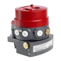
6 INSTALLING AND DETACHING THE
ACTUATORS
6.1 General
Different Metso actuators can be mounted using suitable
brackets and couplings. The valve can be operated, for
example, by actuators of the E, B1 or Quadra-Powr series.
6.2 Installing EC and EJ actuators
The actuator is attached to a valve via an ISO 5211 standard
mounting interface. The actuator is adapted to the valve shaft
with a separate bushing. The bushing (II + II) is a two-piece
cone-shaped bushing, which is tightened firmly with a tight-
ening screw (I) around the valve shaft.
Mount the bushing and the tightening screw from
the mounting interface side of the actuator, accord-
ing to Fig. 38. Insert cylindrical pins (III) in the bush-
ing slots, these must be directed into the
corresponding slots in the actuator during tighten-
ing. Before the installation of the bushing and the
tightening screw, remove impurities such as old
threadlocking material from the threads of the tight-
ening screw, and apply Loctite 225 or similar thread-
lock carefully to the threads, as shown in Fig. 38. Turn
the tightening screw from inside the actuator shaft
using a suitable hex key, Fig. 39.
Fig. 36 Using a former to check shaft position
Fig. 37 Locking a pin
Table 3 Screw torques (for lubricated screws)
Screw
M6
UNC 1/4
M8
UNC 5/16
M10
UNC 3/8
M12
UNC 1/2
M16 M29
Torque,
Nm
8 183565170330
CAUTION:
Pressure testing should be carried out using equipment
conforming to the correct pressure class!
CAUTION:
Beware of the segment movement!
Fig. 38 Cone bushing installation
Fig. 39 Tightening of the cone bushing

 Loading...