3 R 74 en 7
The actuator must not touch the pipeline, because pipeline
vibration may damage it or interfere with its operation.
In some cases, for instance when a large-size actuator is
used or when the pipeline vibrates heavily, supporting the
actuator is recommended. Contact Metso Flow Control
business for further information.
3.4 Commissioning
Ensure that no dirt or foreign objects are left inside the
valve or pipeline. Flush the pipeline carefully. Keep the
valve entirely open during flushing.
Check all joints, pipings and cables.
Check that the actuator, positioner and limit switches are
correctly adjusted. Refer to their installation, operation and
service manuals.
4 MAINTENANCE
4.1 Maintenance general
Although Metso’s Neles valves are designed to work under
severe conditions, proper preventative maintenance can
significantly help to prevent unplanned downtime and in
real terms reduce the total cost of ownership. Metso recom-
mends inspecting the valves at least every five (5) years.
The inspection and maintenance interval depends on the
actual application and process condition.
The inspection and maintenance intervals can be specified
together with your local Metso experts. During this periodic
inspection the parts detailed in the Spare Part Set should
be replaced.
Time in storage should be included in the inspection inter-
val.
Maintenance can be performed as presented below. For
maintenance assistance, please contact your local Metso
office. The part numbers in the text refer to the exploded
view and to the parts list in Section 10, unless otherwise
stated.
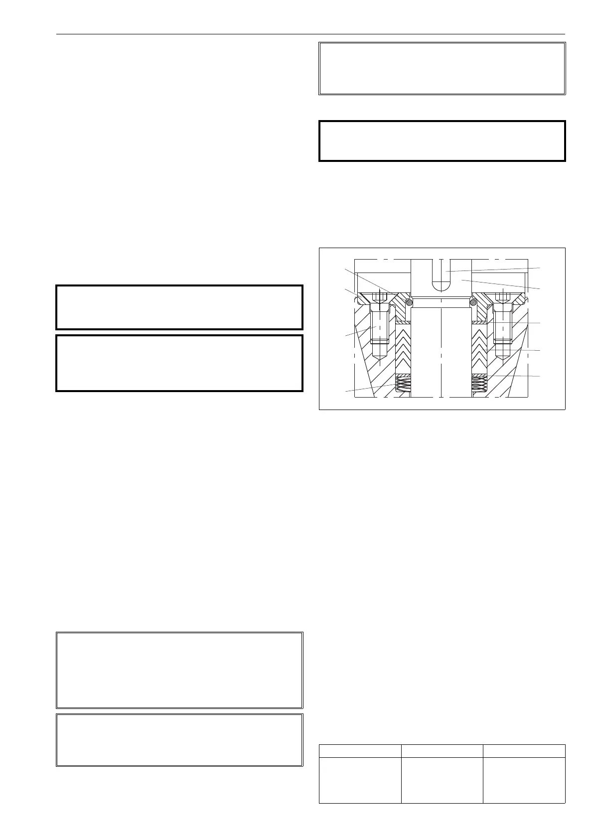
4.2 Replacing the gland packing
4.2.1 RA series
In gland packing, V-ring set (20), tightness is ensured by
pressure caused by the wave spring (32). See Fig. 17.
The gland packing must be replaced when leakage occurs
through the gland (9).
Make sure the valve is not pressurized.
Remove the actuator from the valve shaft acc. to the
instructions given in the actuator’s manual.
Remove the key (13) from the drive shaft (11). Unfas-
ten the screws (25) and the gland (9).
Remove the retainer (30) from the drive shaft. Avoid
to damage the shaft’s surface.
Remove the upper sheet ring (31).
Remove the old packing rings (20) using a pointed
pin. Avoid to damage the sealing surfaces.
Remove the lower sheet ring (31) and the wave
spring (32).
Clean the packing ring counterbore.
Mount the spring (32) and the lower sheet ring (31)
into the counterbore.
Mount the new packing rings (20) one by one on the
shaft (11) using the gland (9) as a tool. The keyway
and shoulder must not damage the packing rings.
Mount the upper sheet spring (31).
Mount the retainer (30) in the groove of the shaft.
Avoid to damage the surface of the shaft.
Fasten the gland (9) with the screws (25) and tighten
them according to the Table 2.
Mount the key (13) on the shaft (11).
CAUTION:
Observe the safety precautions mentioned in Section
1.8 before maintenance!
CAUTION:
When handling the valve or the valve package as a
whole, bear in mind the weight of the valve or the
entire package.
NOTE:
When sending goods to the manufacturer for repair, do
not disassemble them. Clean the valve carefully and flush
the valve internals. For safety reasons, inform the manu-
facturer of the type of medium used in the valve (include
material safety datasheets (MSDS)).
NOTE:
In order to ensure safe and effective operation, always use
original spare parts to make sure that the valve functions
as intended.
NOTE:
For safety reasons, replace pressure retaining bolting if the
threads are damaged, have been heated, stretched or cor-
roded.
CAUTION:
Do not dismantle the valve or remove it from the pipe-
line while the valve is pressurized!
Fig. 17 Gland packing
Table 1 Torques for gland screws
Thread Torque, Nm Width across flats
M6
M8
UNC 1/4
UNC 5/16
8
18
8
18
4 mm
5 mm
5/32"
3/16"

 Loading...